Xano Sweeting | Portfolio
Formula SAE Motorsports (Chief Electrical Engineer)
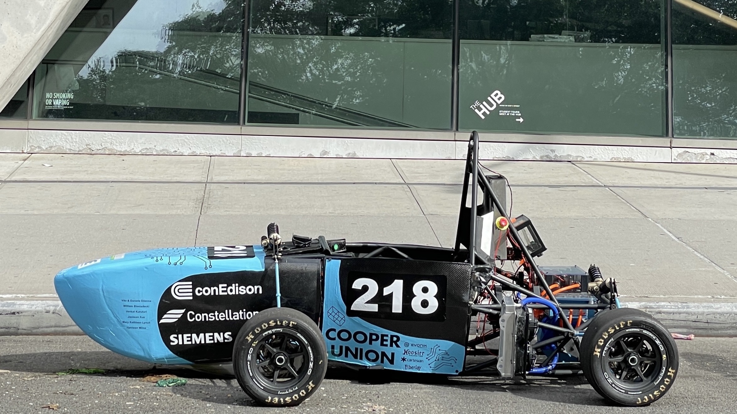
I stepped up to the role of Chief Electrical Engineer at the start of 2023. What we had so far was essentially a chassis with suspension design. Over the course of 5 months I designed, iterated and tested an entire electric vehicle system.
Battery Module Design
Custom Fuse Design and Testing
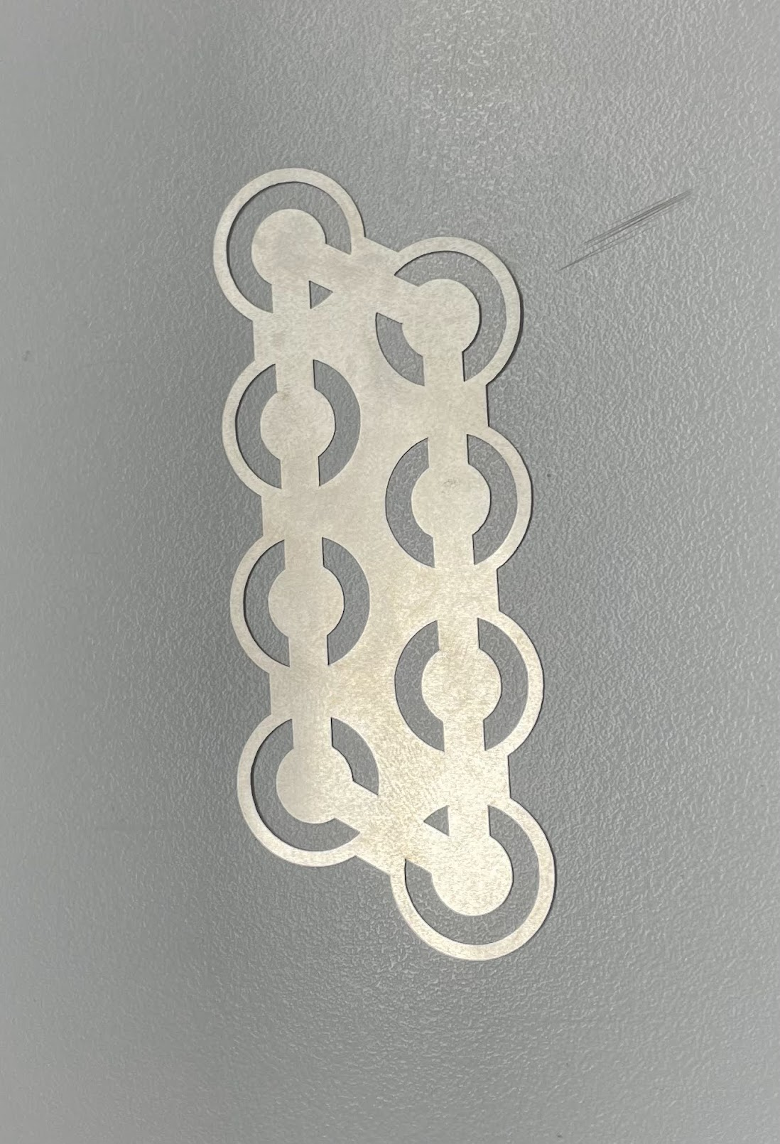
I initially took on the challenge of designing custom battery packs because I believed I could design something cheaper and higher performing than what was offered to most FSAE teams off the shelf. One of the first challenges to solve was cell level fusing.
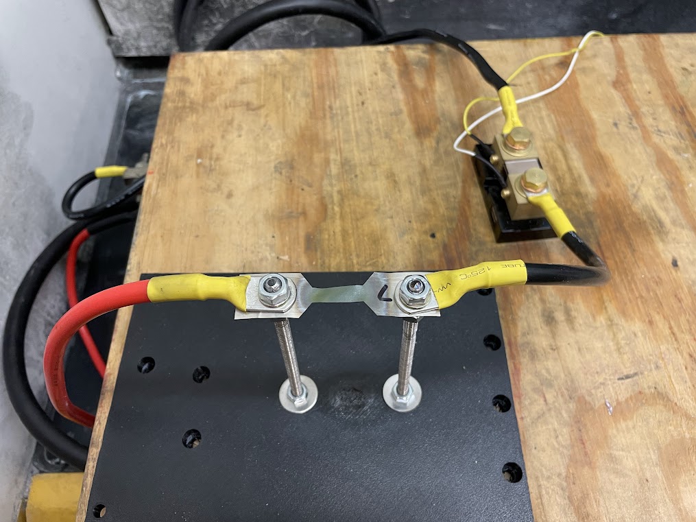
I designed nickel fuses for P42A 27100 battery cells, that I lasercut and then characterized through a series a fuse blowing tests. The tests were conducted by putting the fuse in series with a power supply capable of sourcing large amounts of current, a contactor for opening the circuit and a shunt resistor for measuring the current. Data was recorded using an ossiloscope measuring the voltage drop across the shunt resistor.
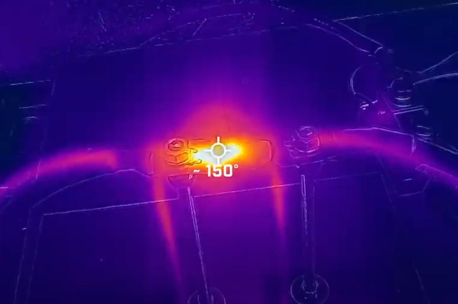
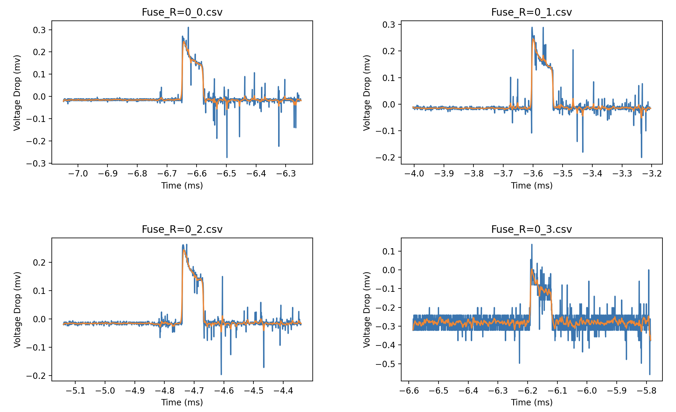
The graphs above correlate to the maximum current tests I ran. The fuse pulled 825Amps from a Marine lead acid battery and blew in roughly 80ms. I plotted and filtered the data using python.
Battery Module M2
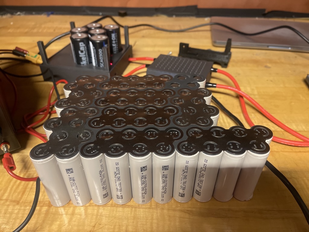
The first and second iteration of the battery pack was designed for extremely tight space constraints while still providing the performance required to excel int he competition.
I manufactured the battery packs by lasercutting nickel conductor plates then gluing the cells together and spotwelding the plates to the cells. The design was extremely hard to manufacture safely and had poor fit and finish. Both aspects were greatly improved on in module M3
Battery Module M3
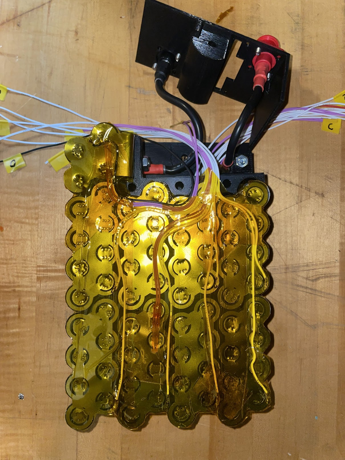
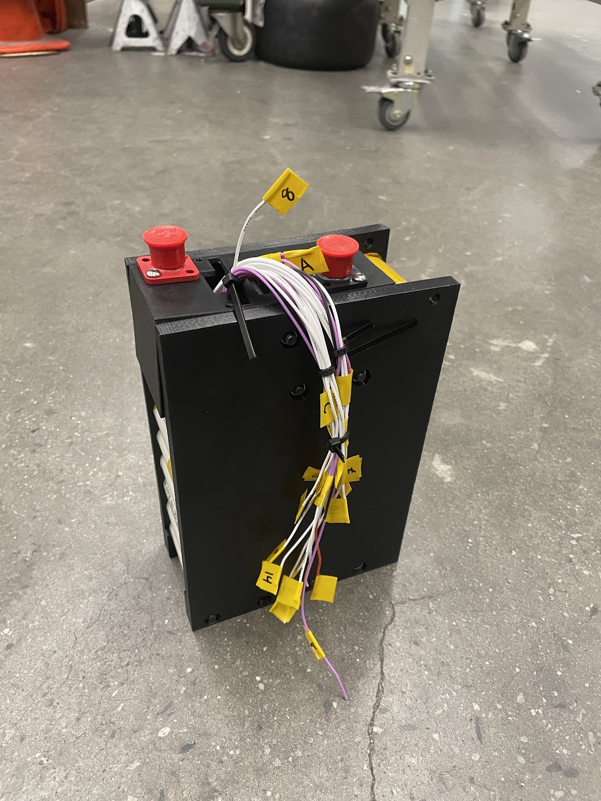
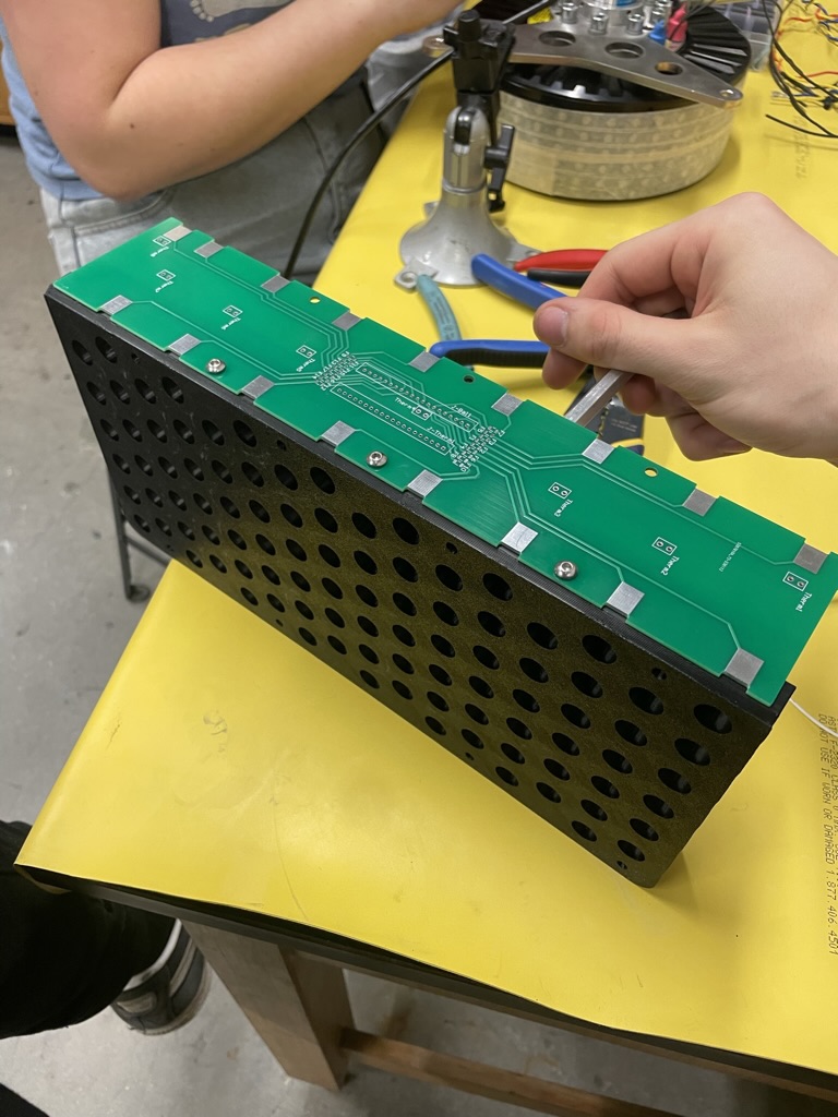
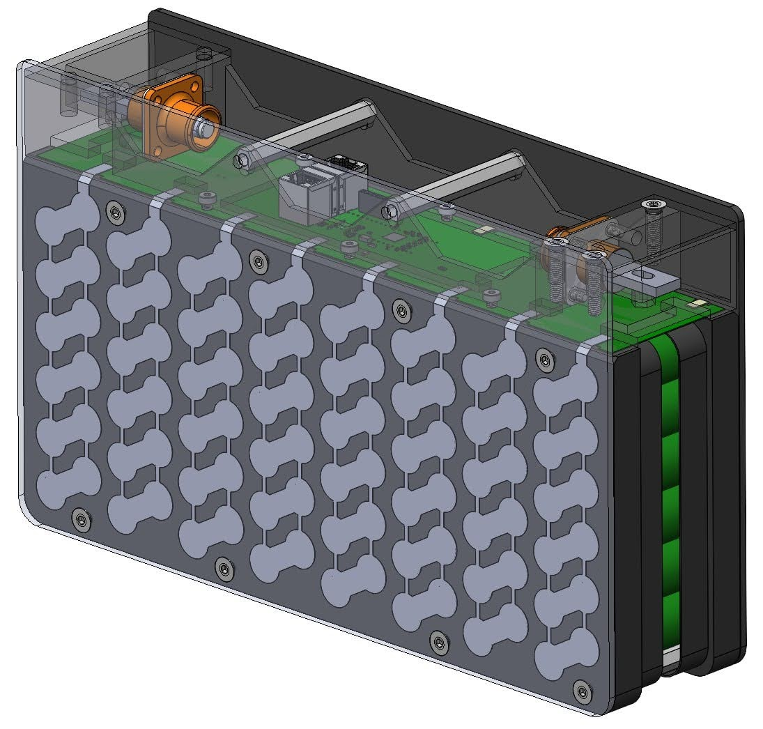
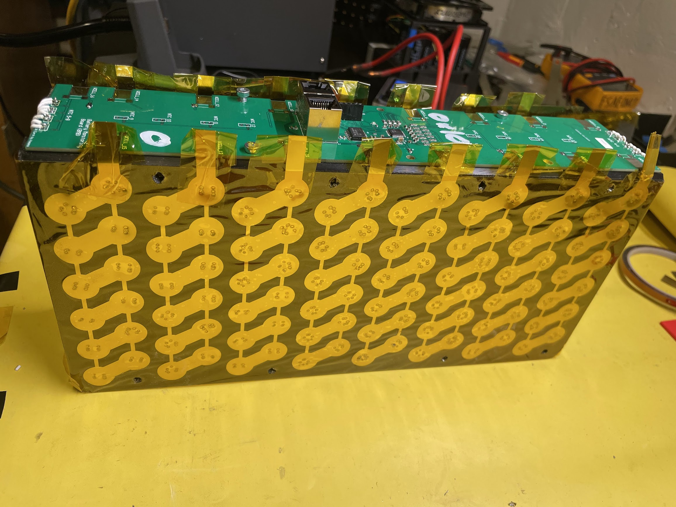
This pack was my redesign with a higher prioritization of manufacturability, safety and structural strength.
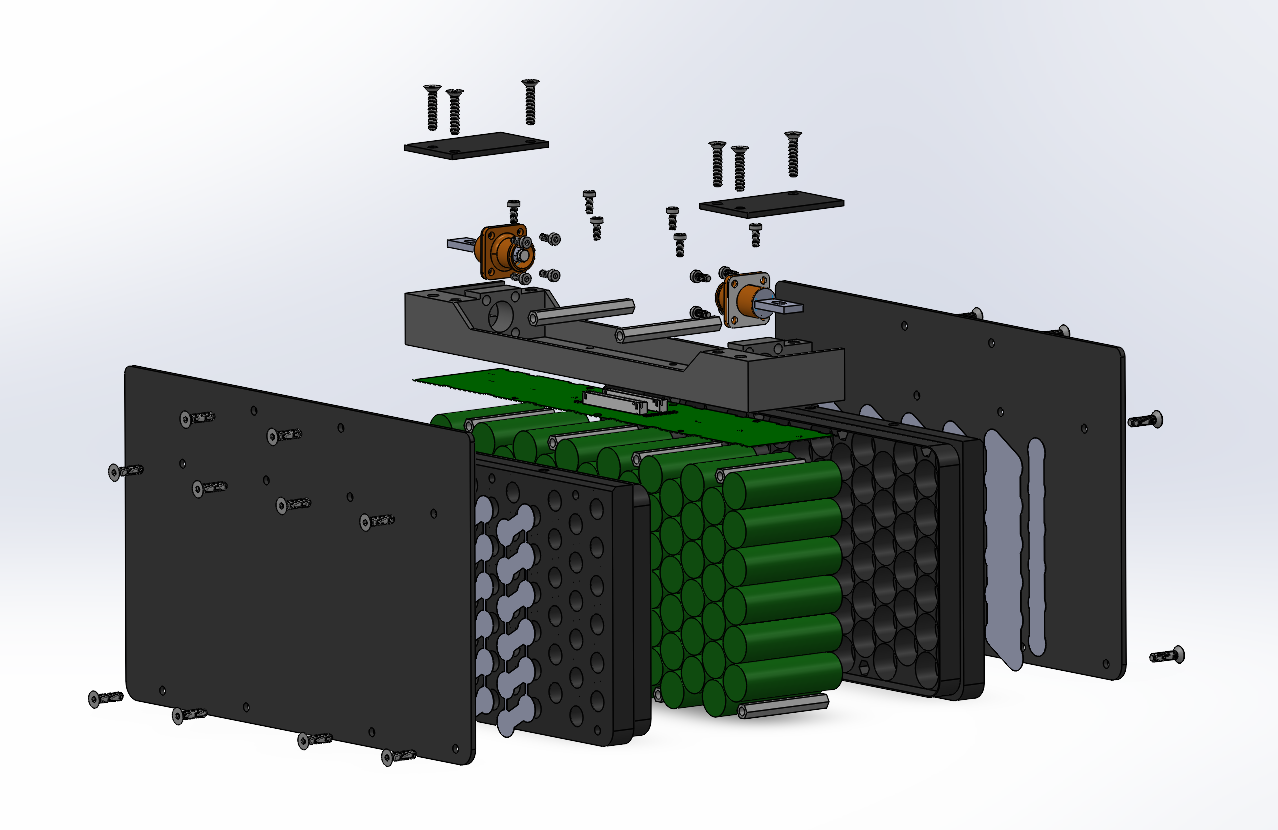
16s 6p battery pack, capable of 15.5kw peak output (270 amps peak at 57.6 Volts). This battery pack is much faster to manufacture than my previous design. It includes flame retardant, thermal potting which ensures thermal homogeneity within the pack as well as added structural and vibration dampening benifits.
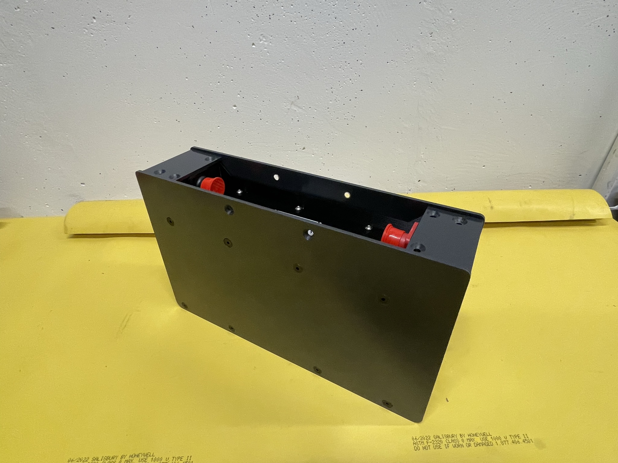
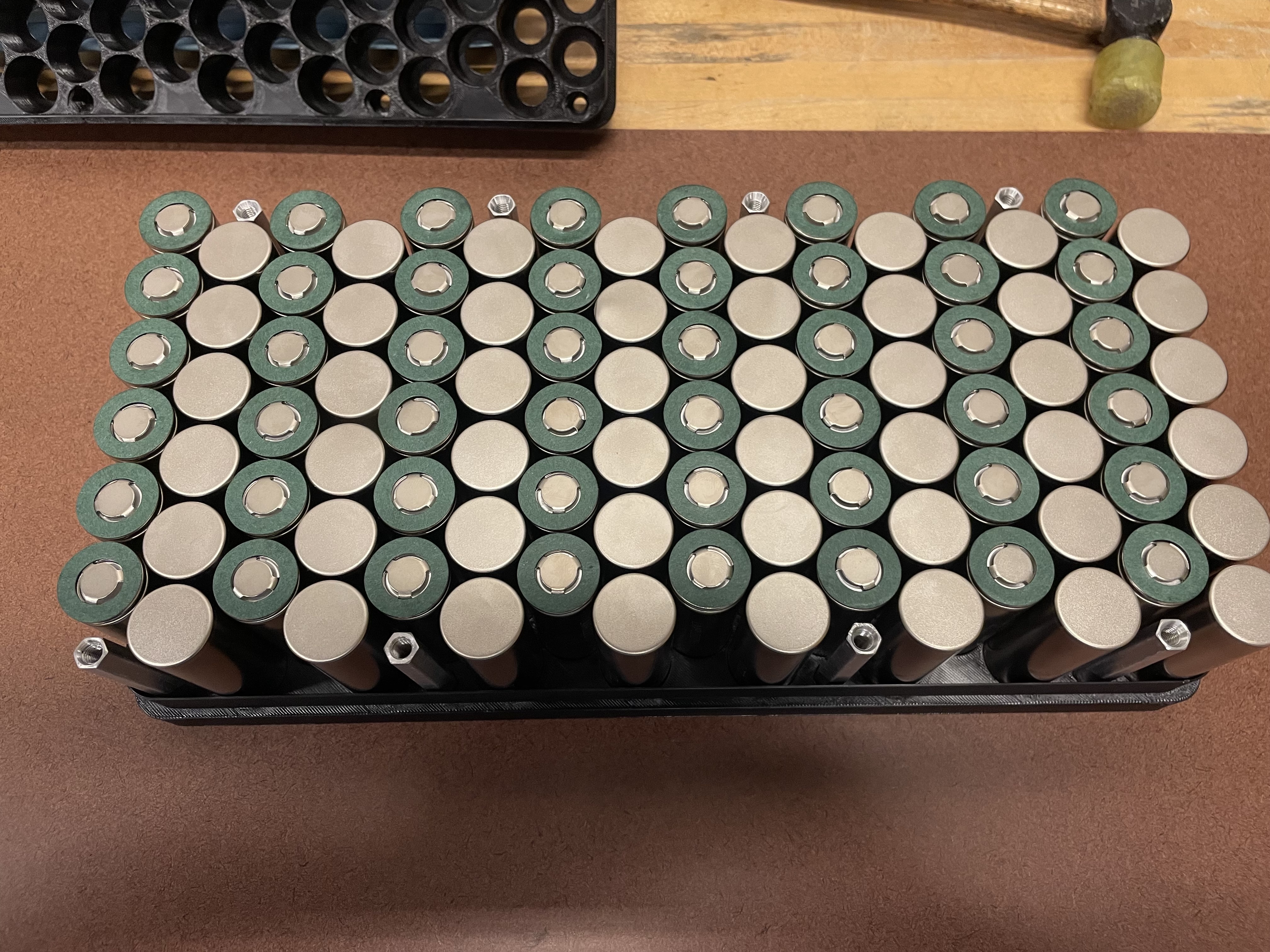
The threaded aluminum standoffs seen interspersed along the edges of the pack took me 5 hours straight to custom machine. Definitely going to try and design around premade spacer lengths next time.
BMS Design
I initally planned to use an off the shelf balancing solution with a breakout board built into the pack. But once we discovered what our team had bought already was not rules compliant we had to shift gears.
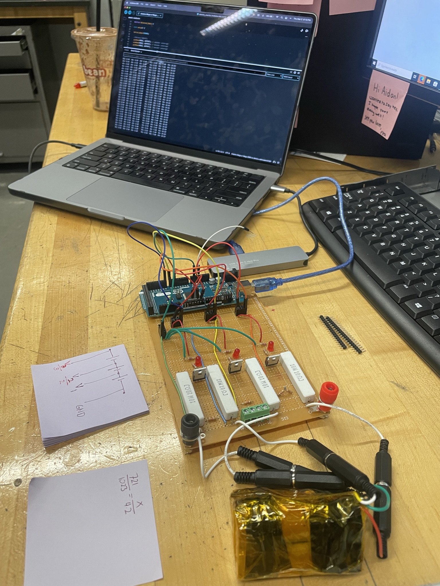
Distributed BMS Prototype in a night (3/2/2023)
I realized our BMS didn’t have the proper Galvanic isolation between modules, so I started figuring out how to make one from scratch. I whipped up a plan for distributed and isolated balancing system using off the shelf balancing ICs (bq7 series). From conception to prototype in about 12 hours. Had to scrounge parts from around the school right before closing so I could solder all night. I did this just as a proof of concept so we could pull the trigger on doing a full design.
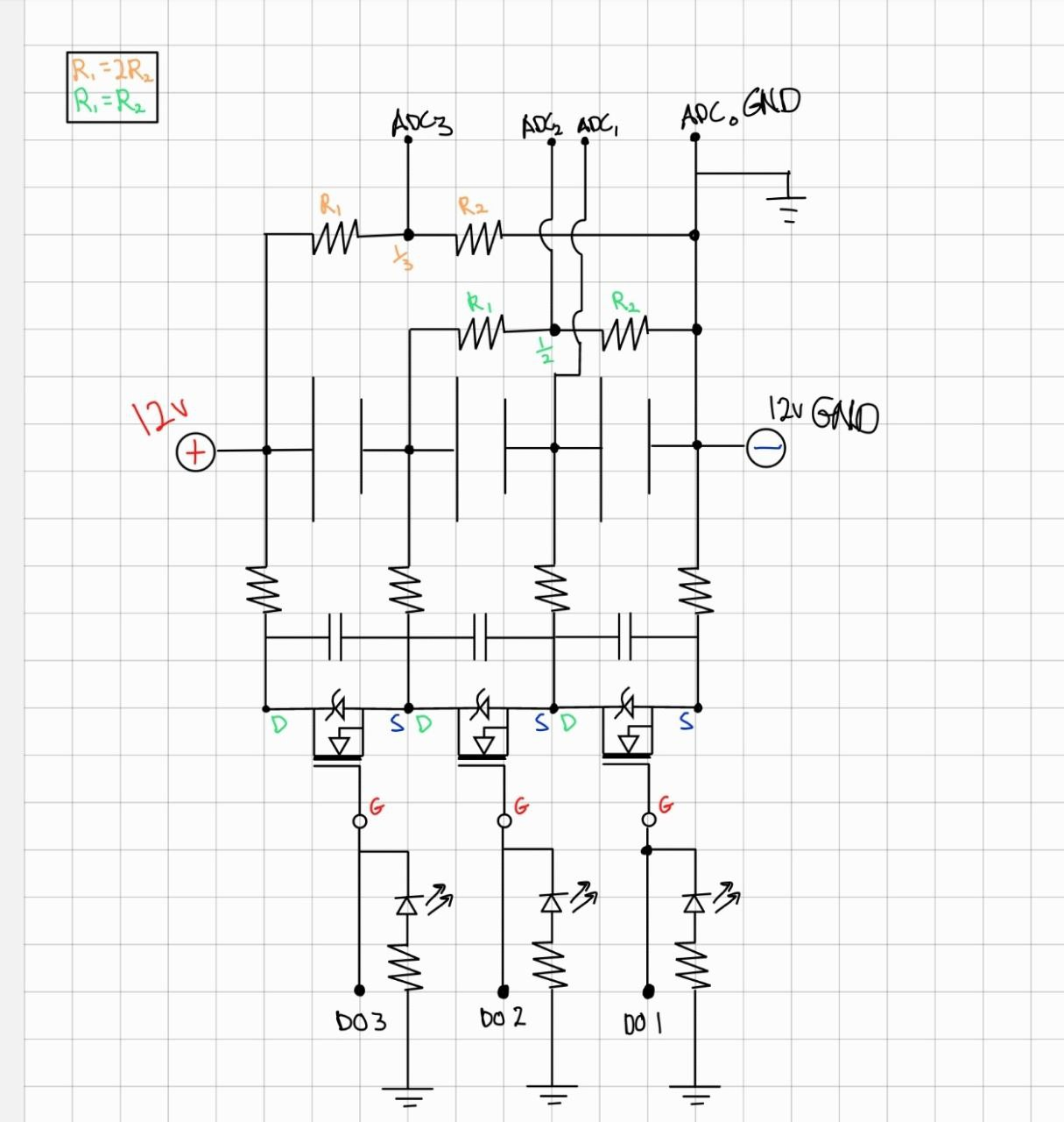
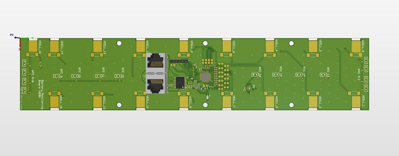
Aftering setteling on a bq7 chip and hacking away at a layout that would fit the module design we came to the board seen below.
Final BMS Design
Assembling these boards greatly improved my smt soldering skills.
Vehicle Design
The battery pack was one of the first components I designed on the car, and I was given all the mechanical constraints and preffered specs when I joined the team. Designing the the entire electrical system architecture with only the rule book as my constraints was much more difficult.
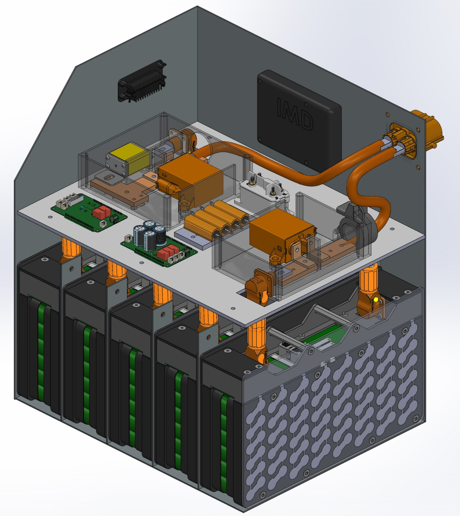
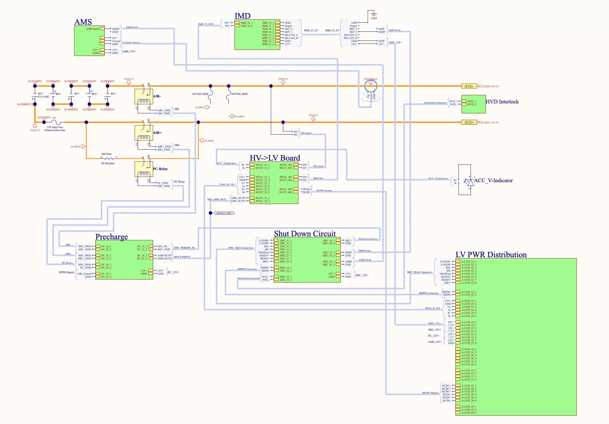
I started my design process with rules requirements of where and when certain system states were meant to be acheived. Below is the accumulator that held the battery packs, battery management system, HV-LV board, contactors, contactor controllers, shutdown controller, and insulation monitor.
Full System Design
Below is one of my first sketches of the full system design. I used altium and draw.io to iterate through and communicate system architecture decisions.

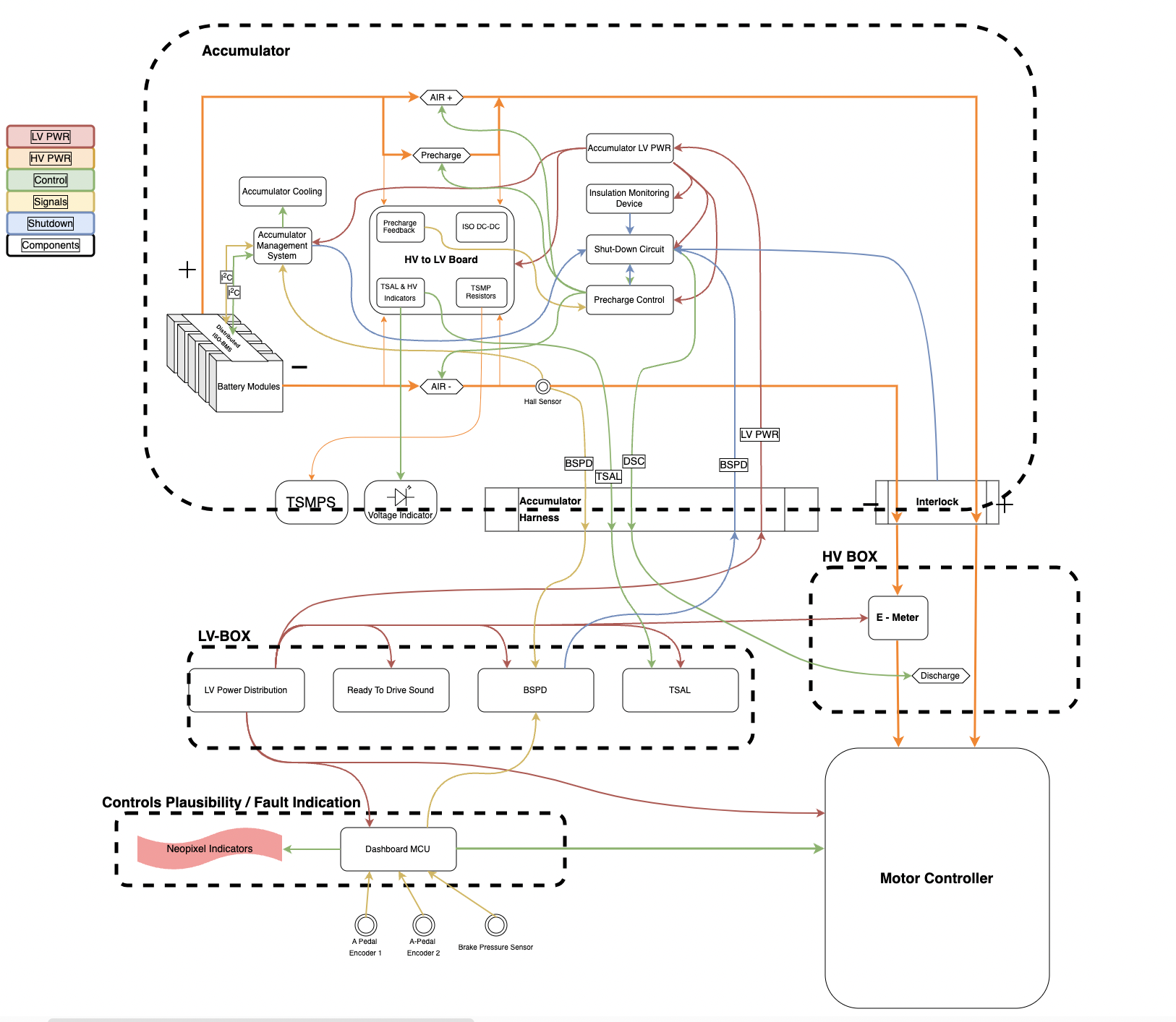
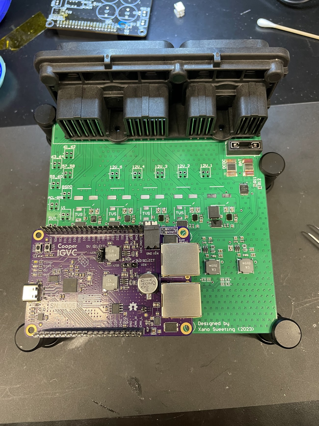
I designed all the different circuits to pair with the open CAN system developed by Cooper’s autonomous drive team. Each board slots into a CAN connected ECU as a breakout board.

Contactor controller & HV<->LV Board
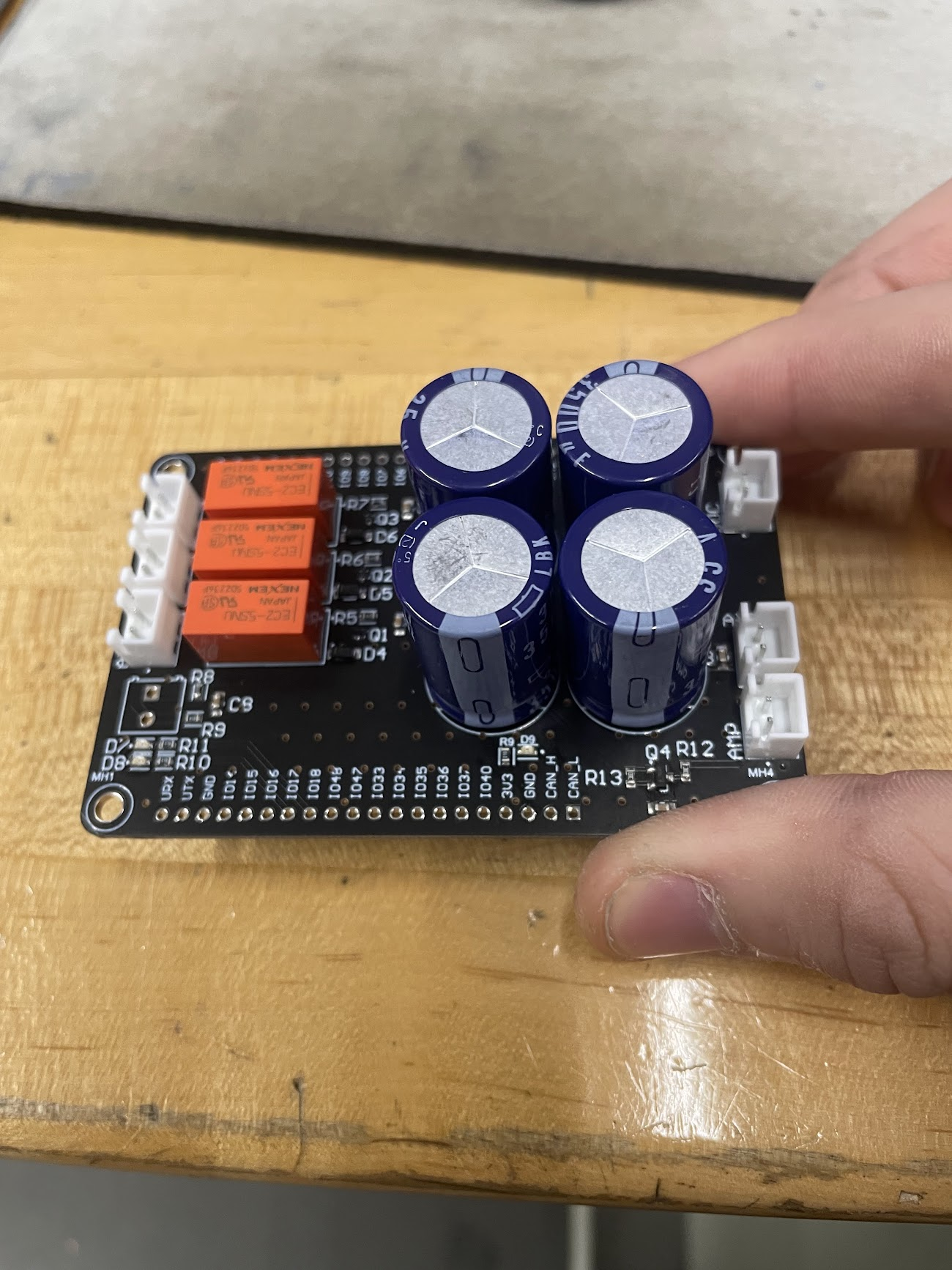
This board was designed to control three contactors. Two high voltage bus contactors and one precharge that allowed for the HV bus to slow charge through a resistor before closing the main contactor. The large caps are to provide a slight delay before the main contactors open once power is cut. This allows time for a safe shutdown command that reduces the risk of opening contactors under load.
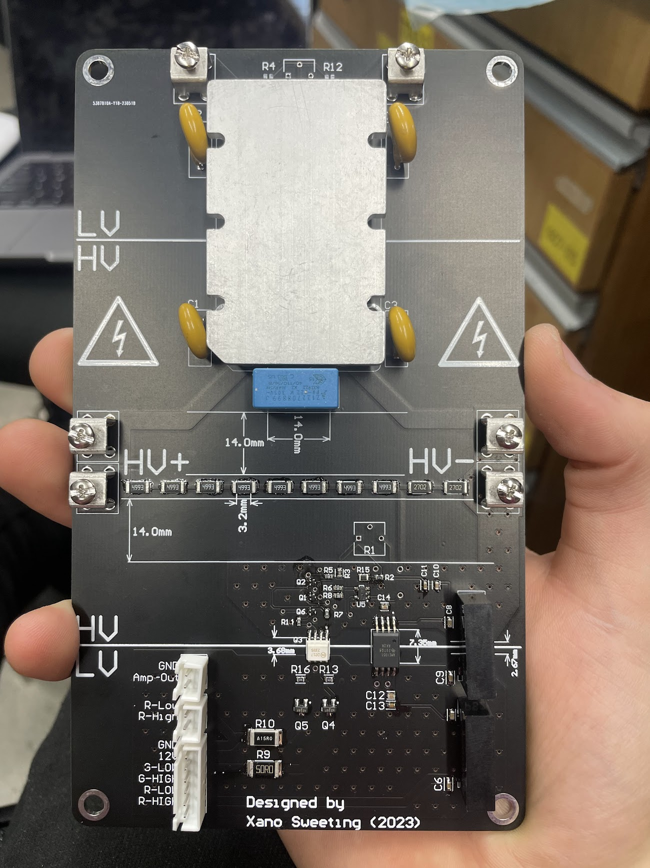
The contactor control board worked in tandem with the HVLV board which provided isolated information about the high voltage bus. This board also contained the HV -> LV DCDC converter and the comparator circuit used to trigger high voltage indicators on the battery box and car. The board was designed to keep all High and low voltage interactions in one isolated place.
Shutdown Circuit
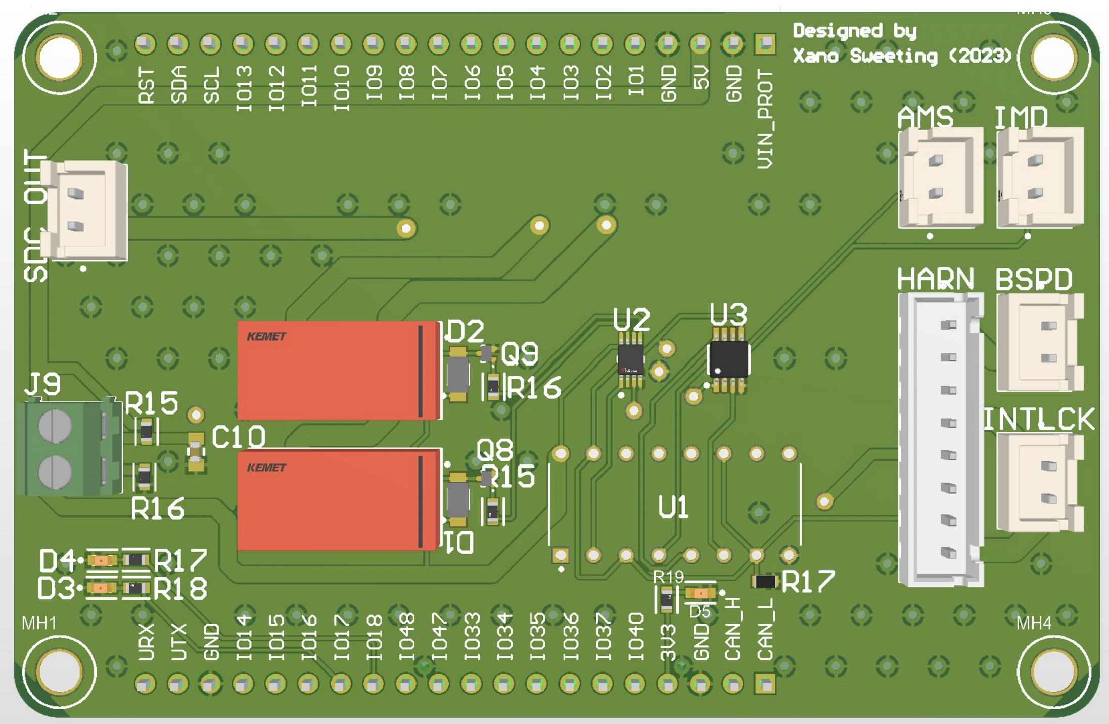
This system is designed to shutdown power to the main contactors on the car whenever there is a critical fault with our main components or an operator uses a shutdown button. A latching IC is used to latch any critical isolation or battery faults in case a transient occurs too quickly or is intermittent. This board also communicates to the entire system a safe shutdown to ensure that the contactors do not open under load.
Power Distribution Board
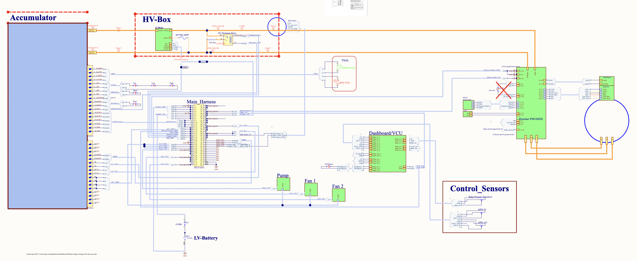
Full harnessing diagram
Like many other parts of this project, I wanted to learn the correct software techniques to produce a good proffessional level project, but it was faster for me to produce something functional than learn the software.
This was a diagram I did containing every connection and pin throughout the car.
Electromechanical packaging
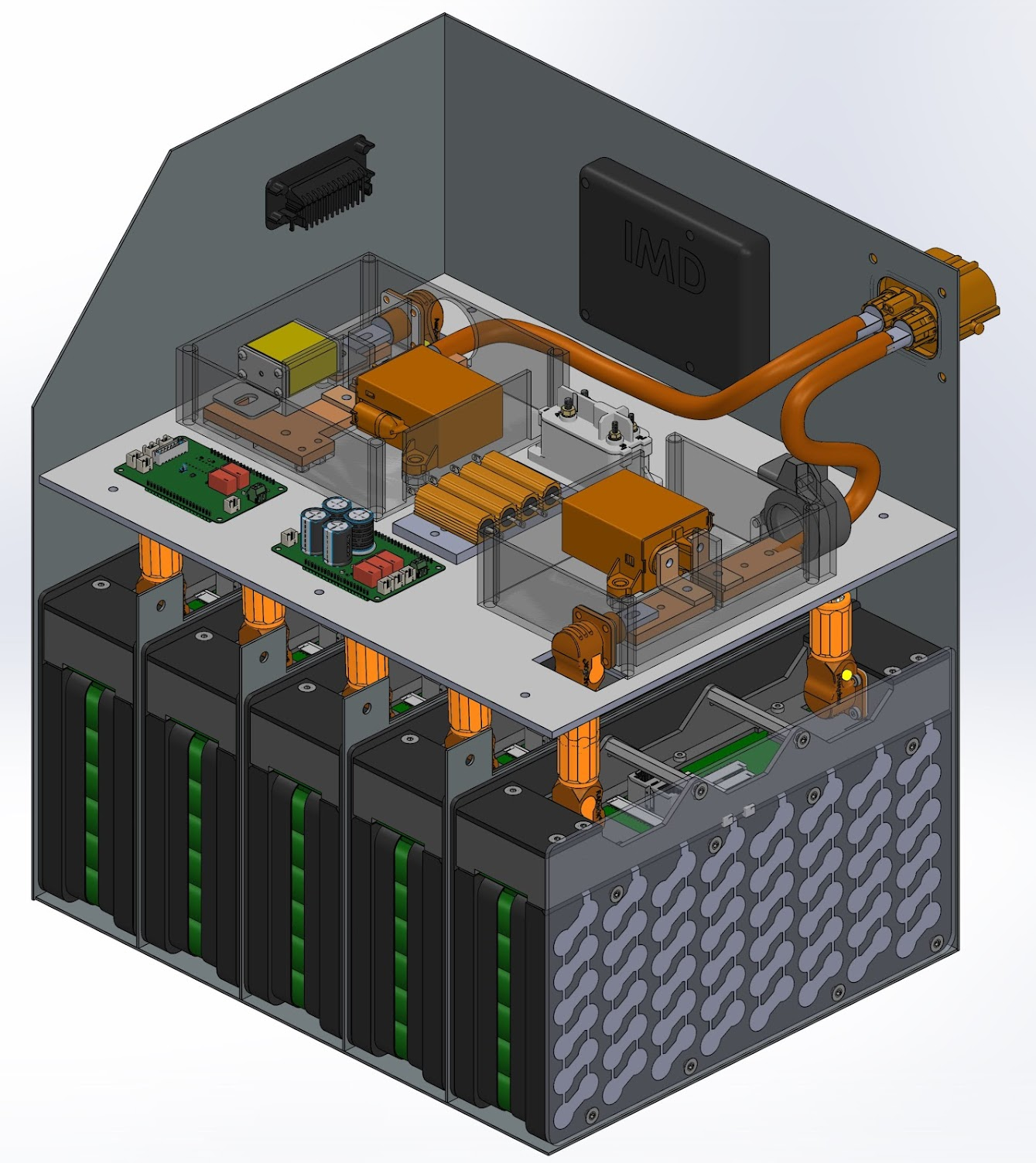
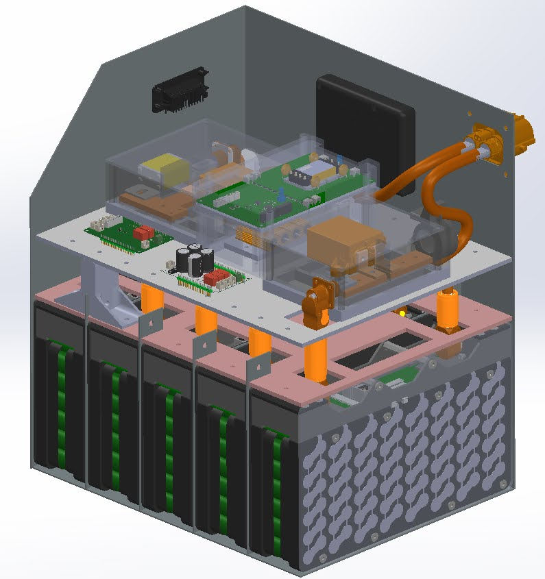
Contactor assembly:
With precharge circuit, galvanicly isolated voltage measurment, DCDC, main fuse, current sensors. All fastners were also insulated.
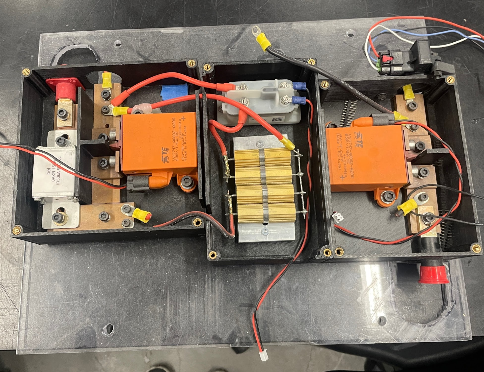
HV box:
Designed with the goal of making competition inspection easy and provide. Houses the capacitance discharge circuit, current sensor and voltage taps.

Exascale Systems
At exascale systems I helped design and fabricate various parts of the motion system for a Czochralski method crystal growth arc furnace. This kind of machine is often used to manufacture large silicon boules for semi conductor wafers. I was helping construct a machine similar to this.
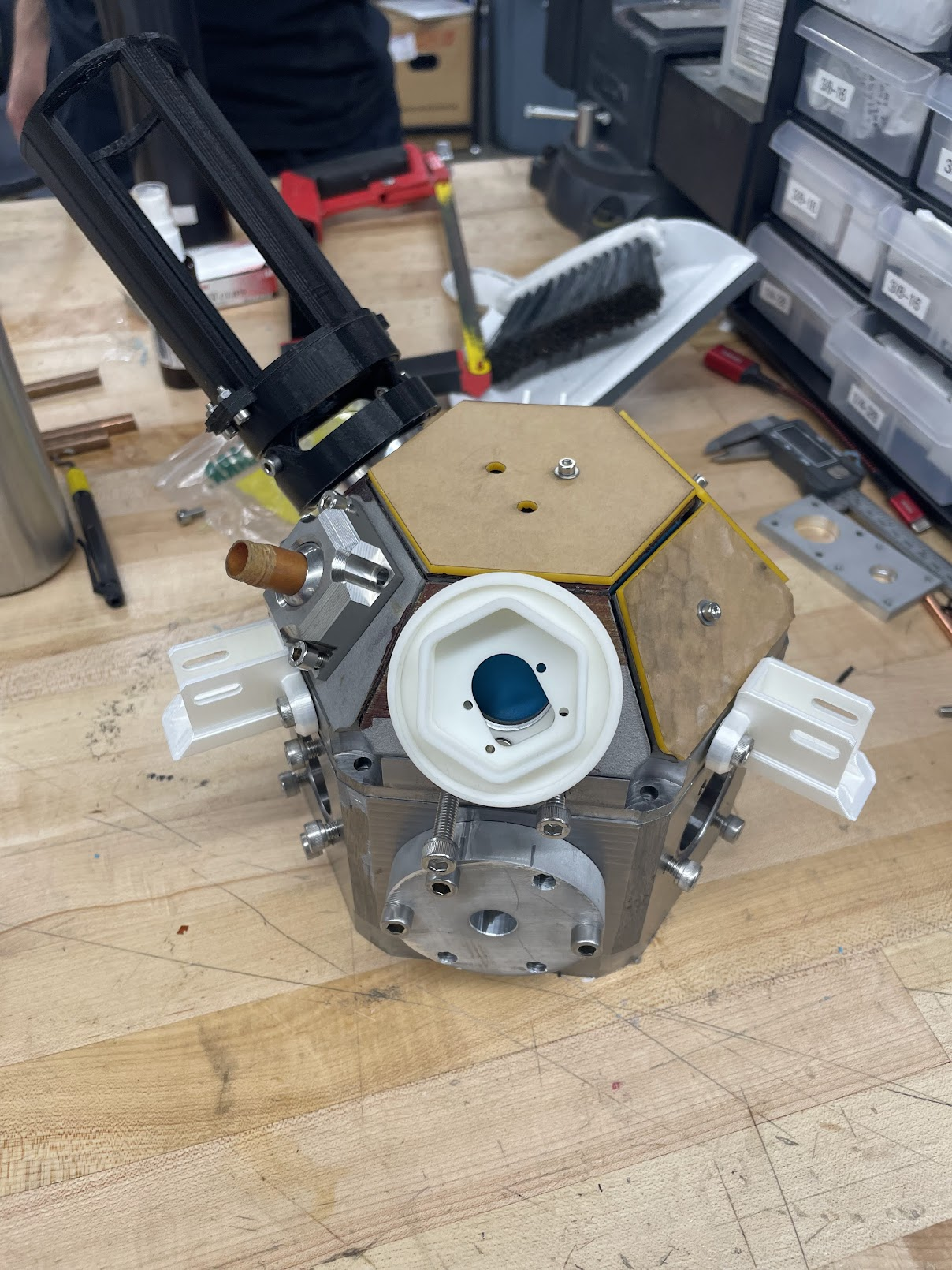
Below is a picture of the arc furnace I worked on, with 3D printed mounts for a shielded raspi camera and as well as mounts for other motion controllers and sensors:
Motion Controller For Arc Furnace
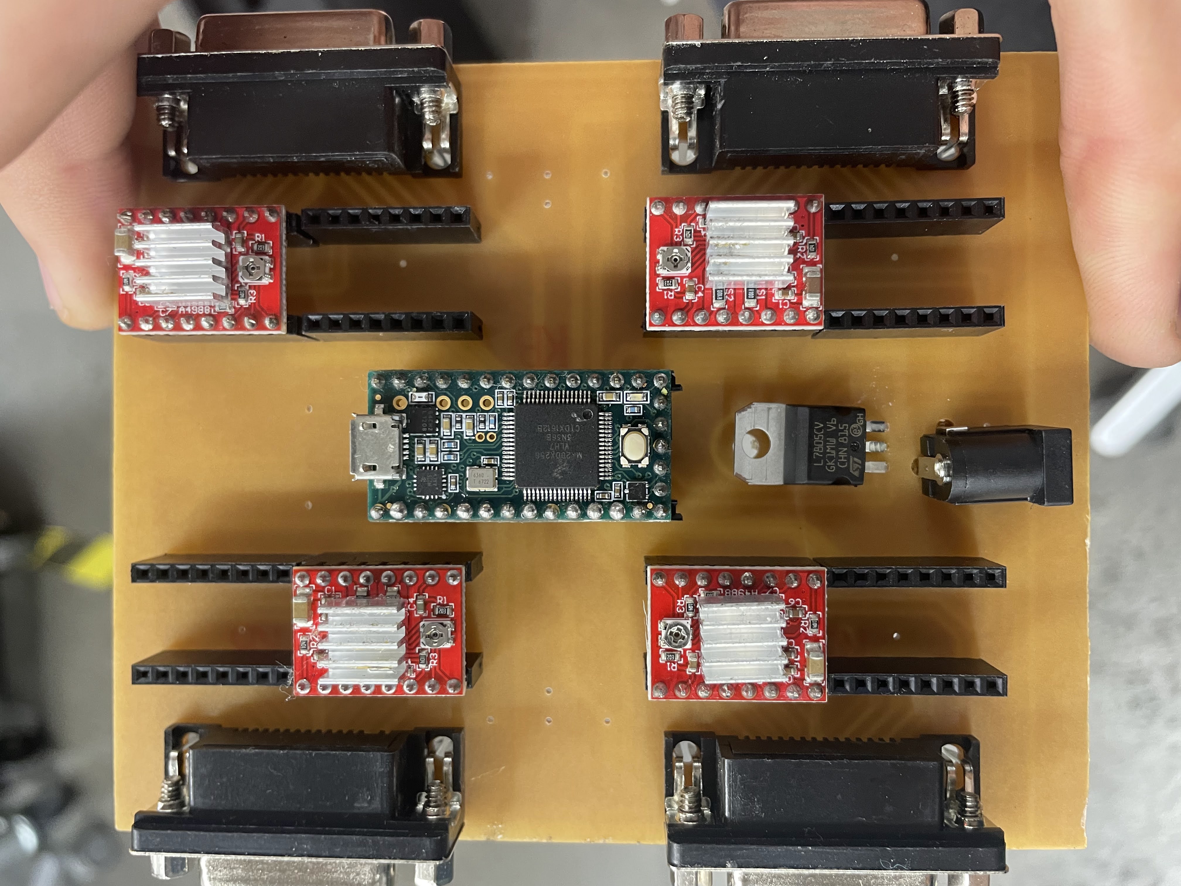
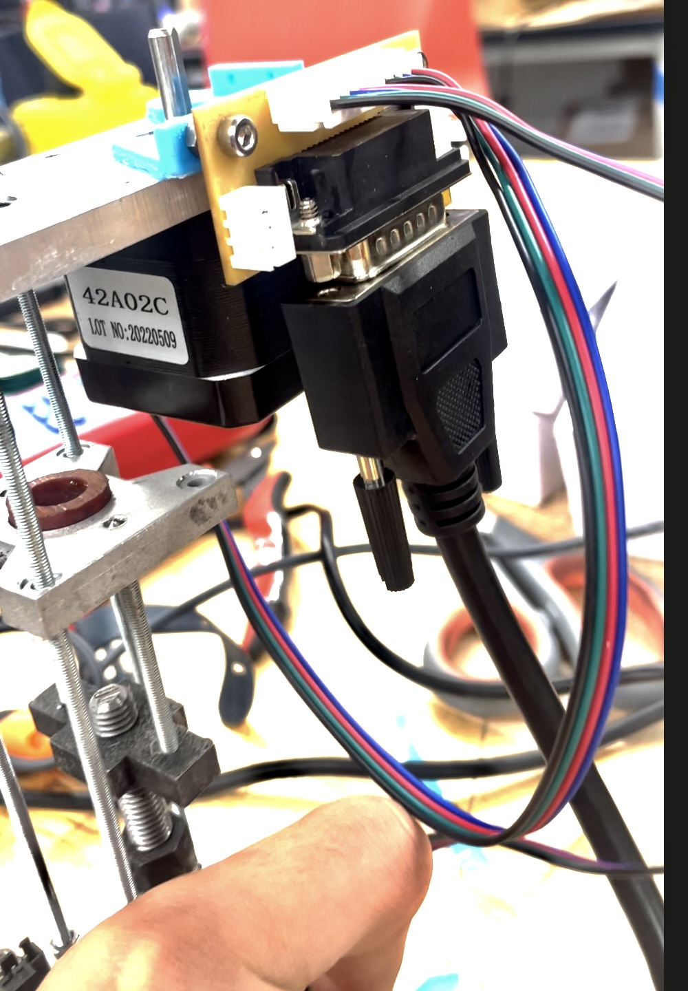
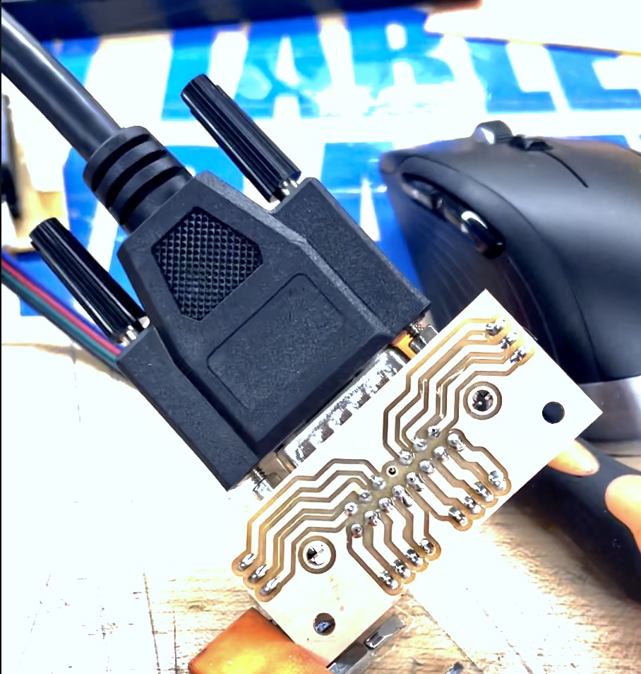
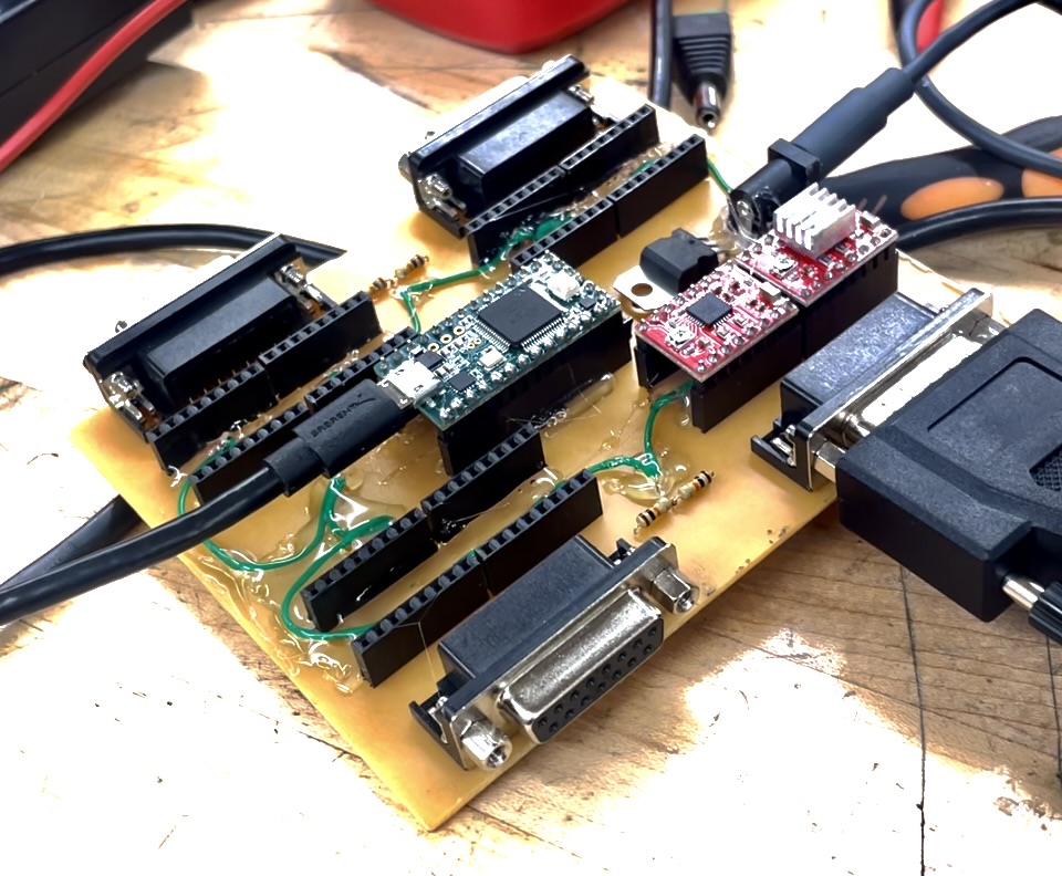
I used DB9 connectors and custom breakout-boards for stepper motors and limit switches. I milled the pcb out of blanks, soldered all the components and programmed the ‘teensy’ microcontroller. There were three electrodes in the arc furnace. Each had one stepper for depth and one for tilt.
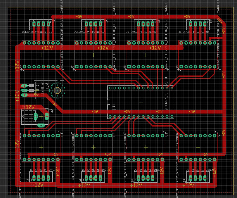
(not the final schematic)
Piezo Flexure Plate
This was an attempt at a precise method of angling diffraction grating plates in an optical setup. A piezo actuator capable of 500N of force was threaded into the center and used to flex the cutout pattern in the plate.
New Amsterdam Metalworks
Robotic Kitchen Hood
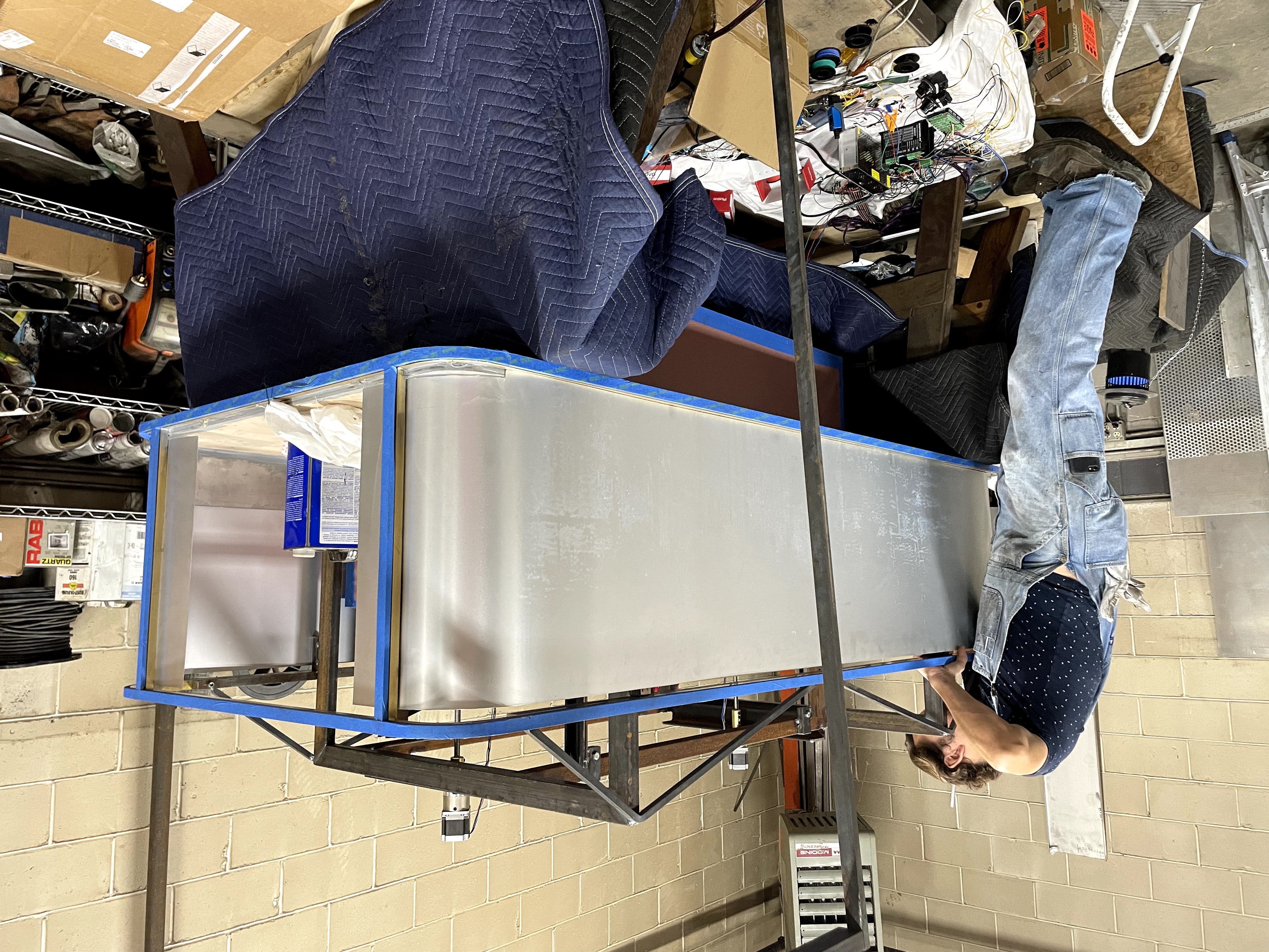
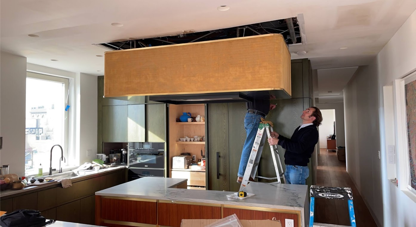
I designed a kitchen hood that actuated up and down at the push of a couple buttons. The project entailed mechanical design, machining, welding, circuity, and controls programming. Limit switches set the range of motion at the top and bottom.
Steel Roof Deck
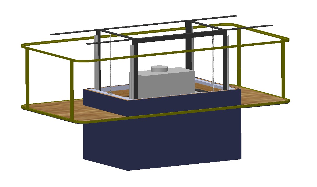
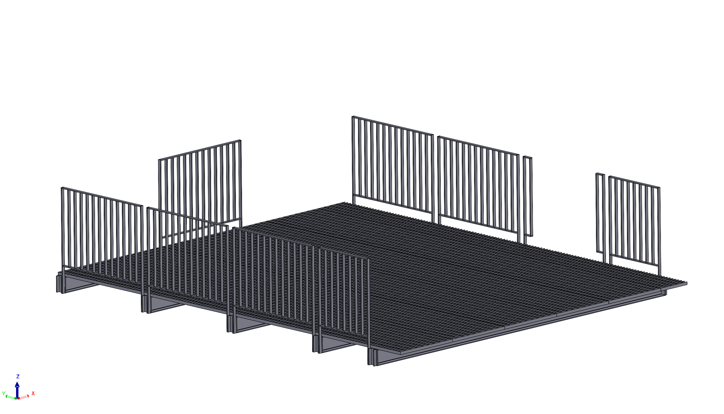
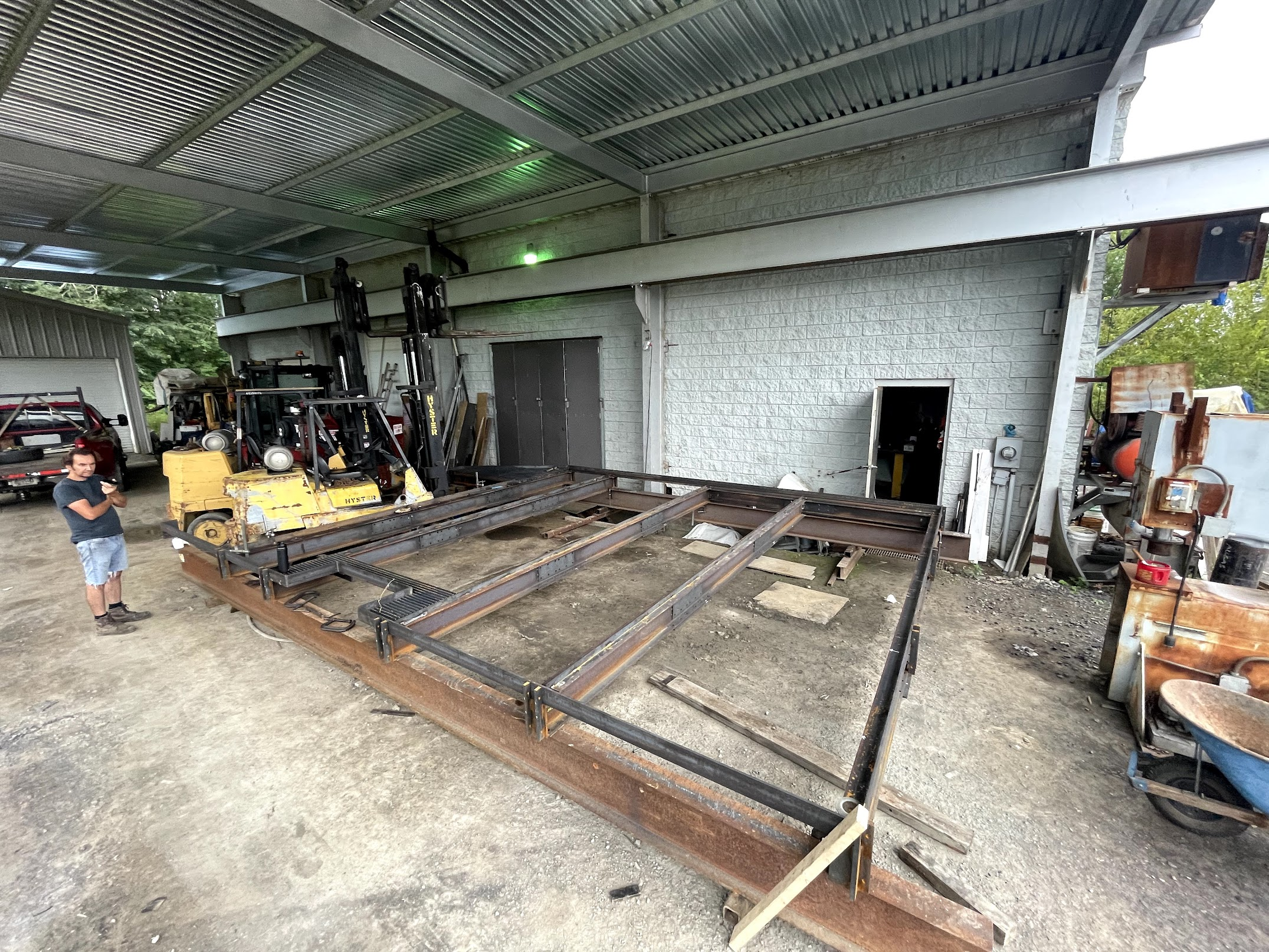
I surveyed the site, made architectural drawings, machined and welded various parts for a steel roof deck structure.
Robotics
Robot In One Night
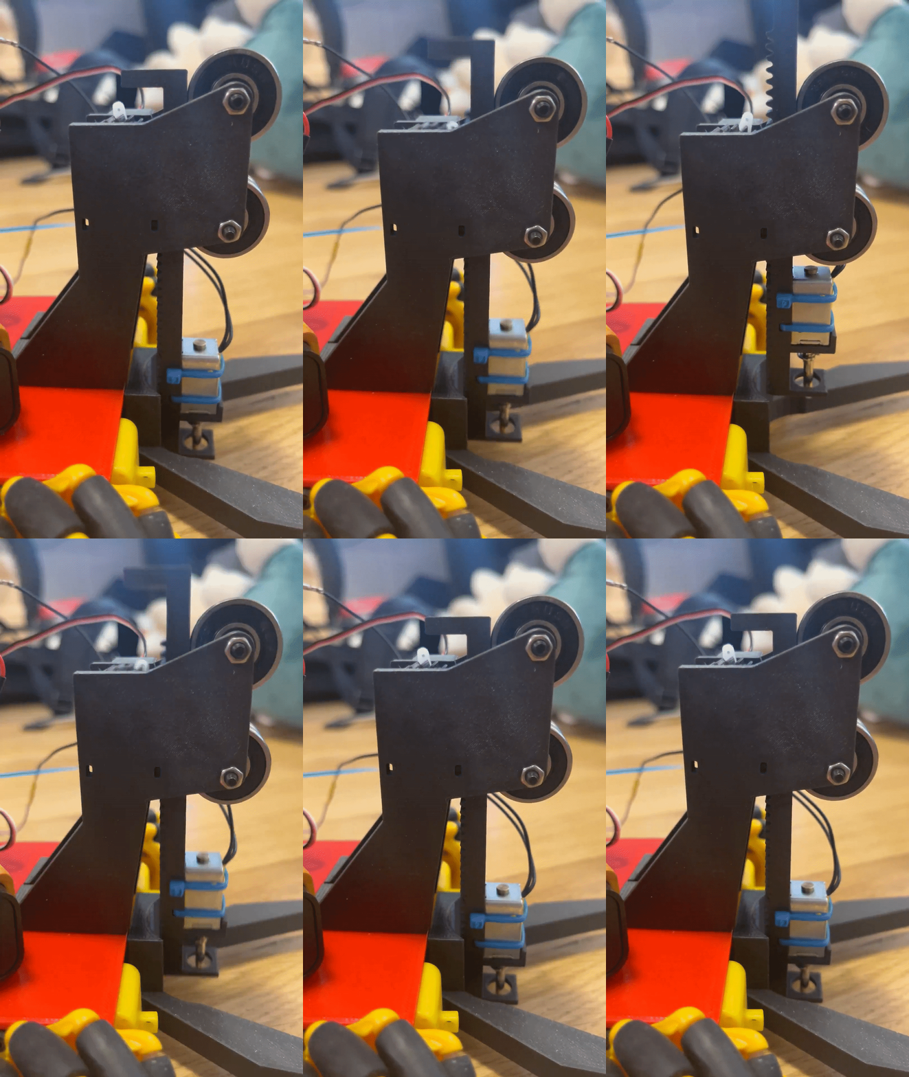
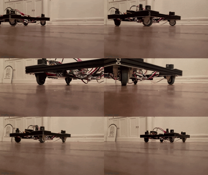
I designed, printed, programmed and built this little bottle cap stacking mecanum robot in one night for a college competition.
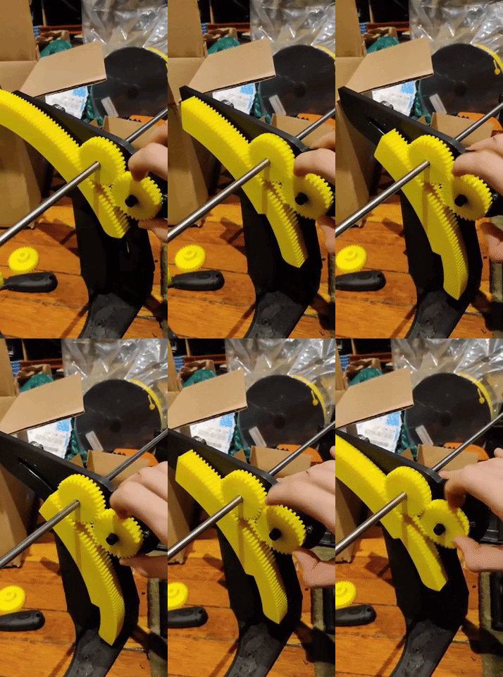
Rack and pinion mechanism in action
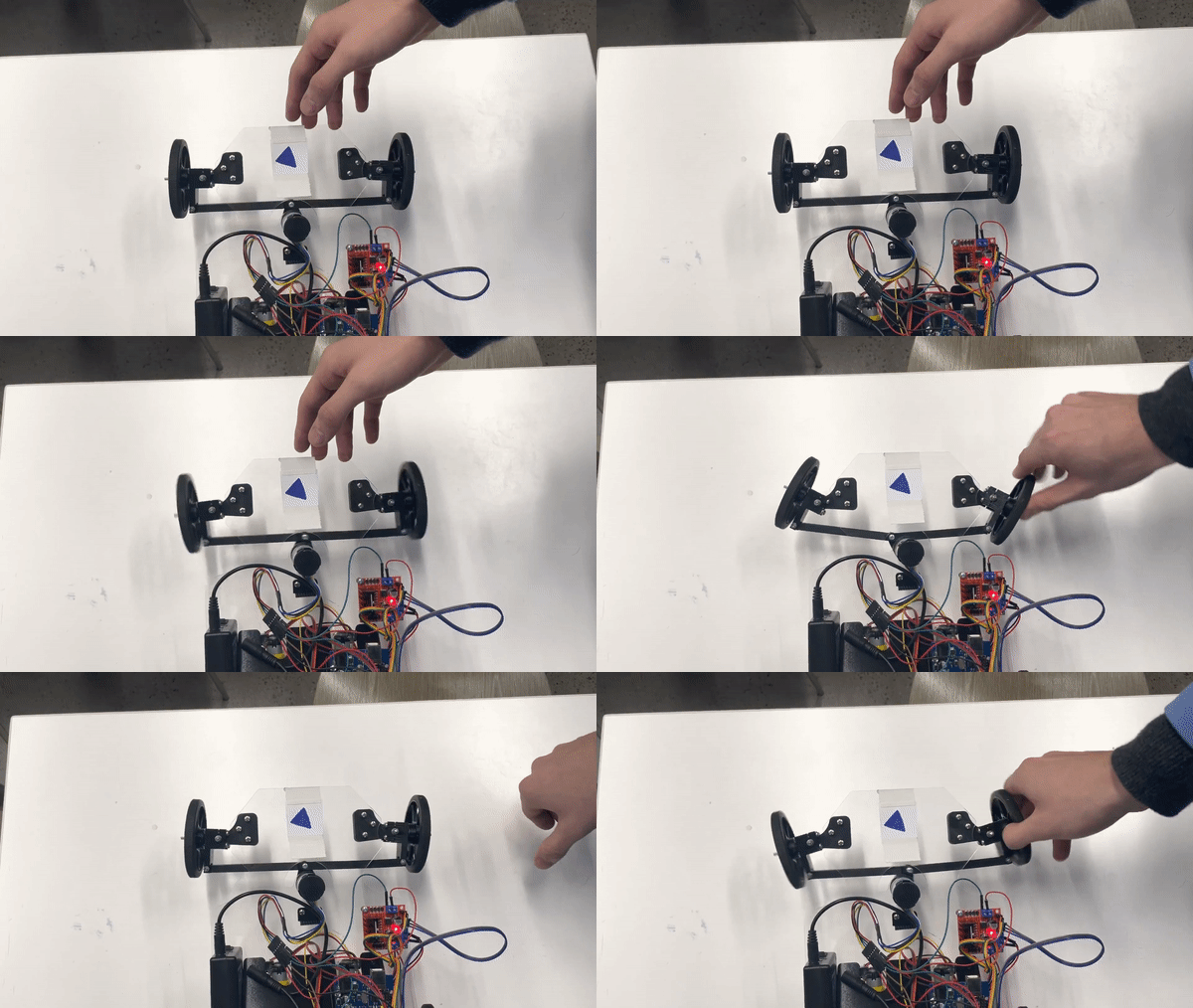
PID Steering Correction
First Robotics League
As Team Captain
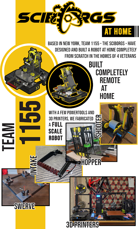
During my senior year of high school (2020 COVID), I led a team in remotely creating an almost fully 3D printed Robot. We built the robot with less than half the budget the team is usually alloted. I slept with 3D printers running 24/7 for a couple months. It was a year that most urban teams didn’t compete, but taking inspiration from James Burton, I knew we could if we wanted.
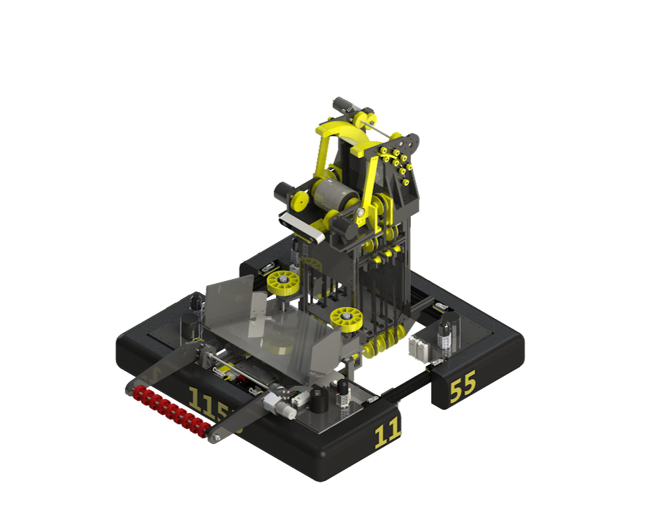
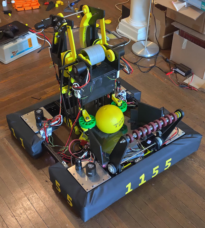
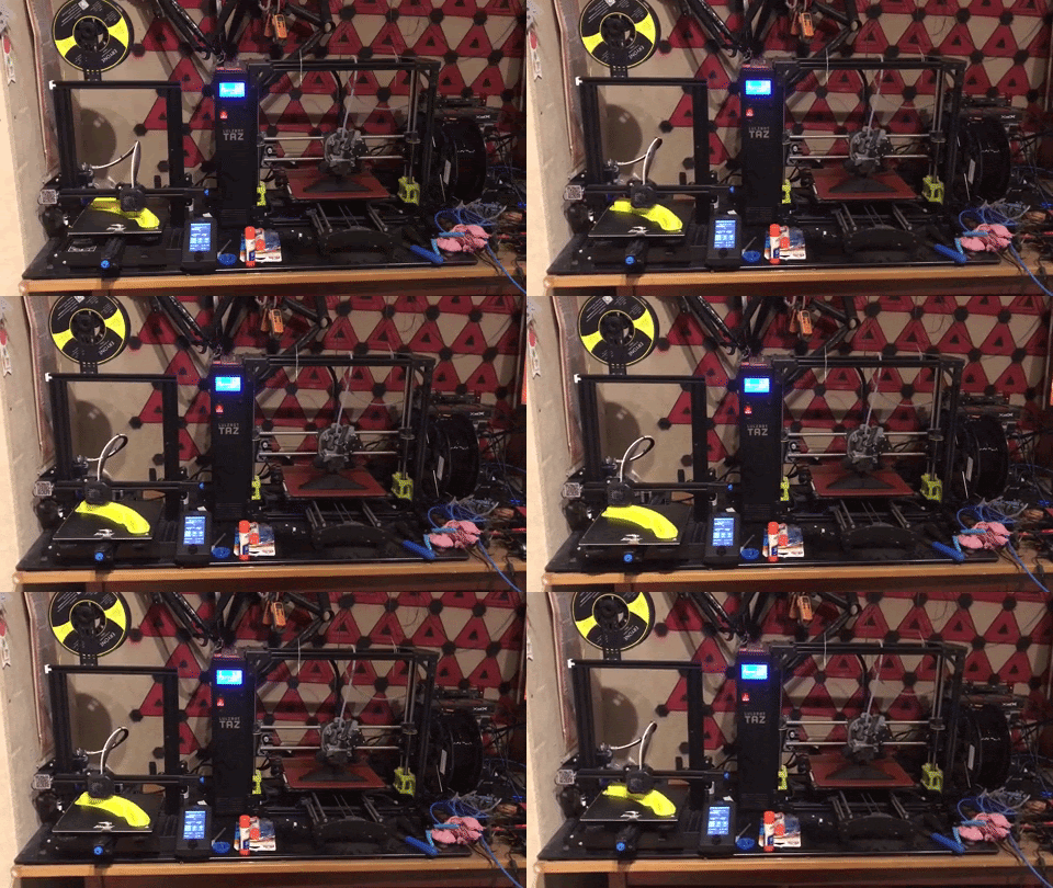
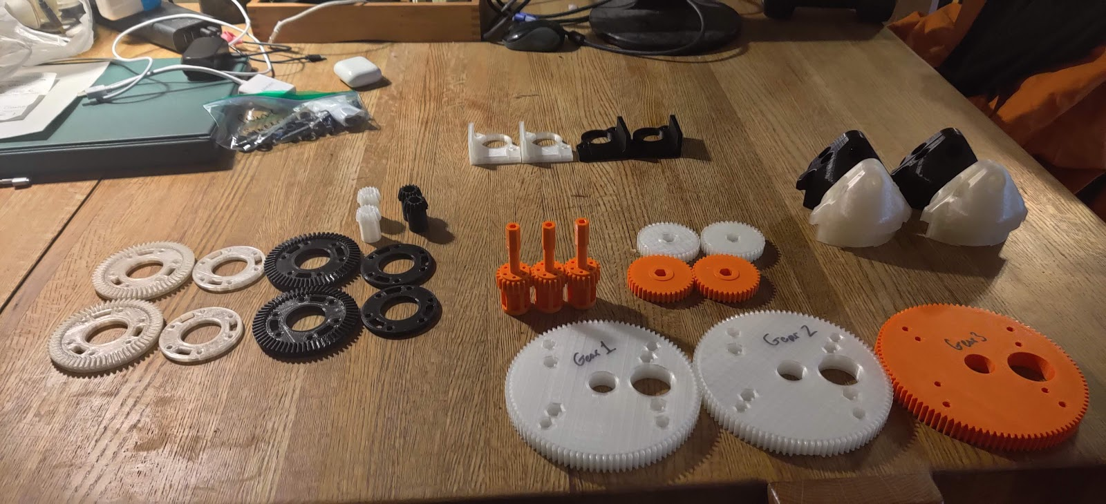
Together we were able to build 5 large mechanisms in seperate homes and then bring those together in mine for a full robot.
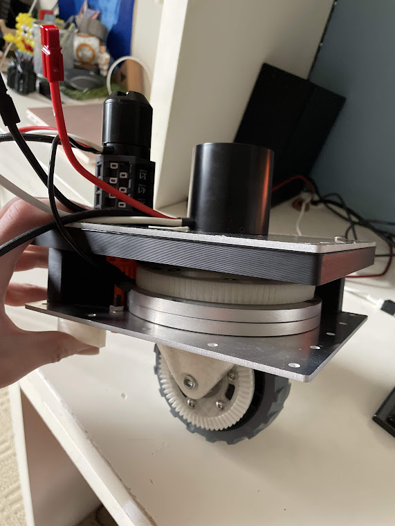
As Team Member
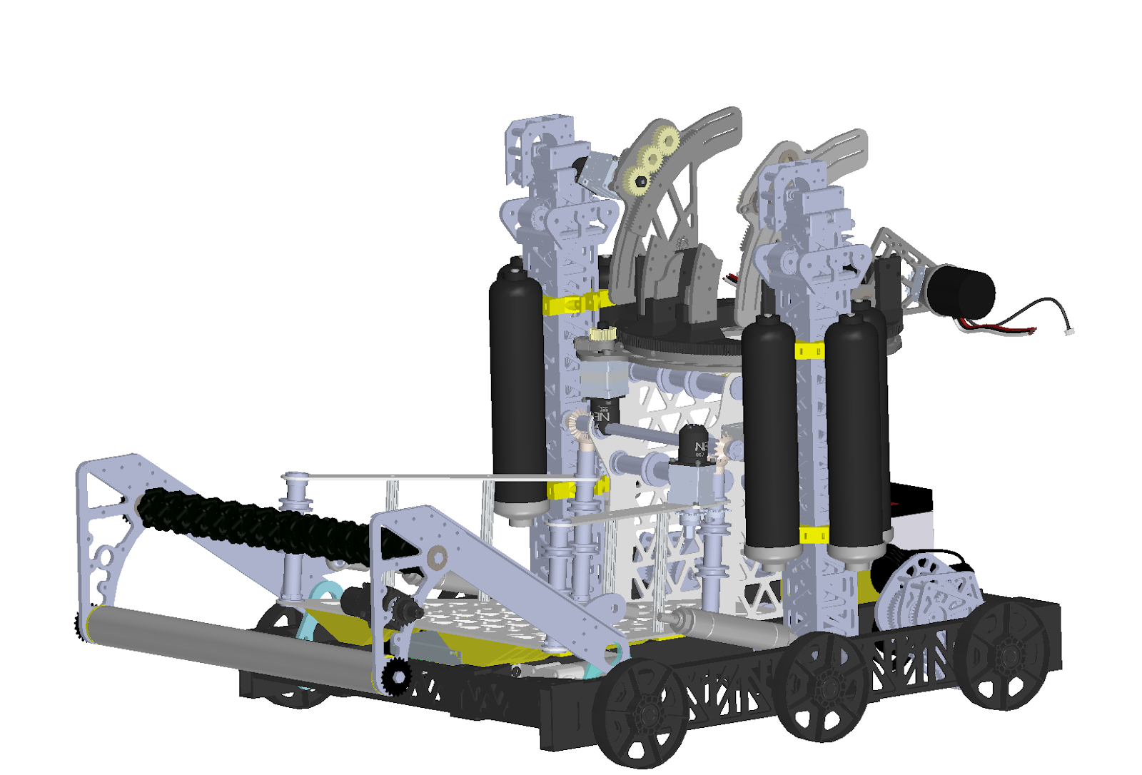
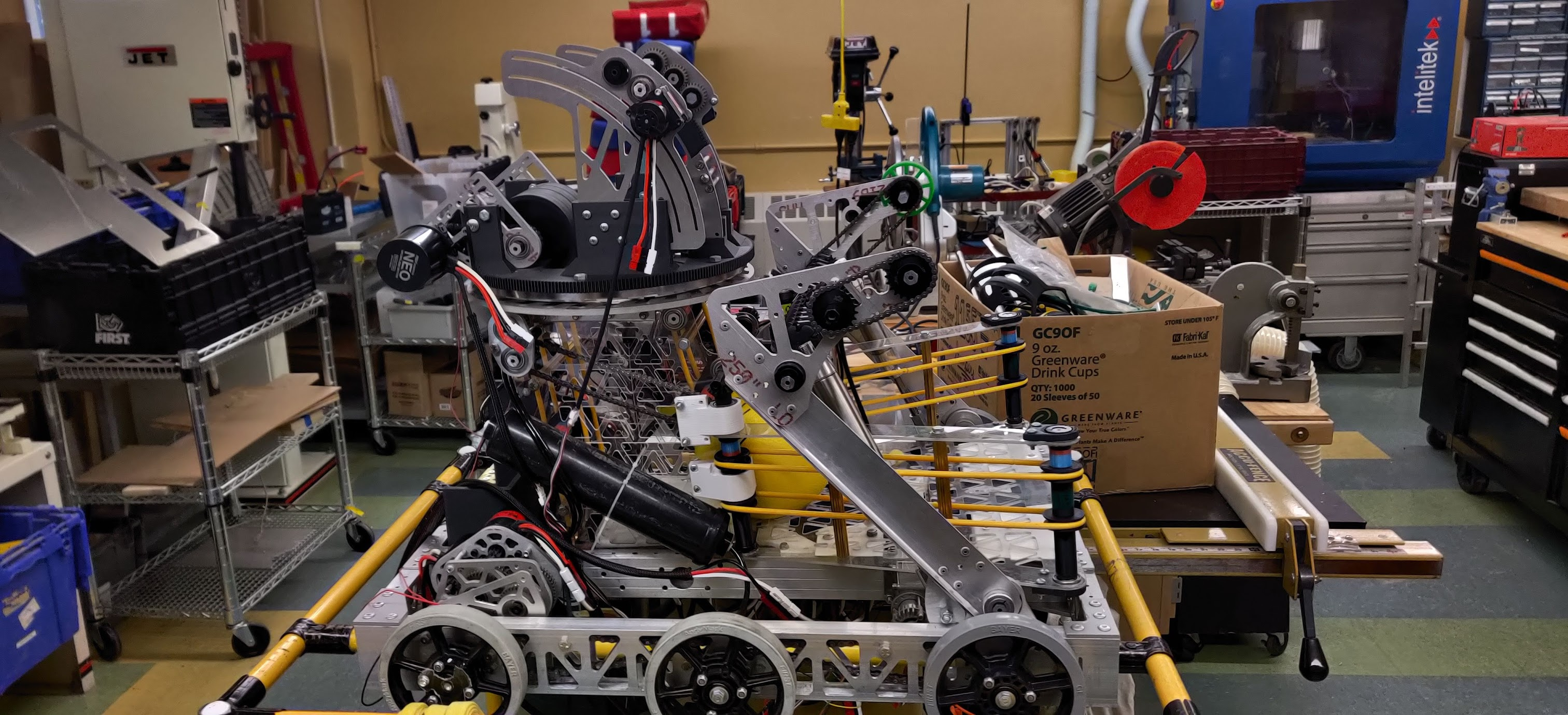
Junior year of highschool,this robot taught me to CAD. I designed the chassis, the roller intake and did the full 1200 part assembly for my team:
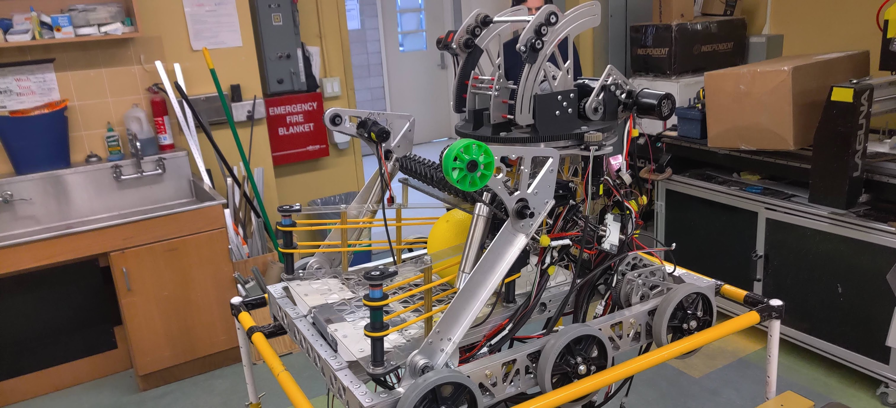
Embedded tank drive
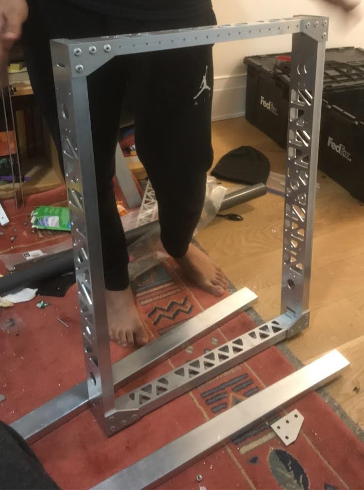
Roller Intake
Misc Projects
Longboard
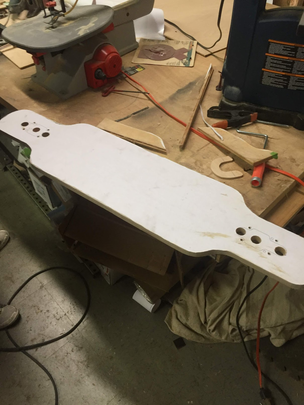
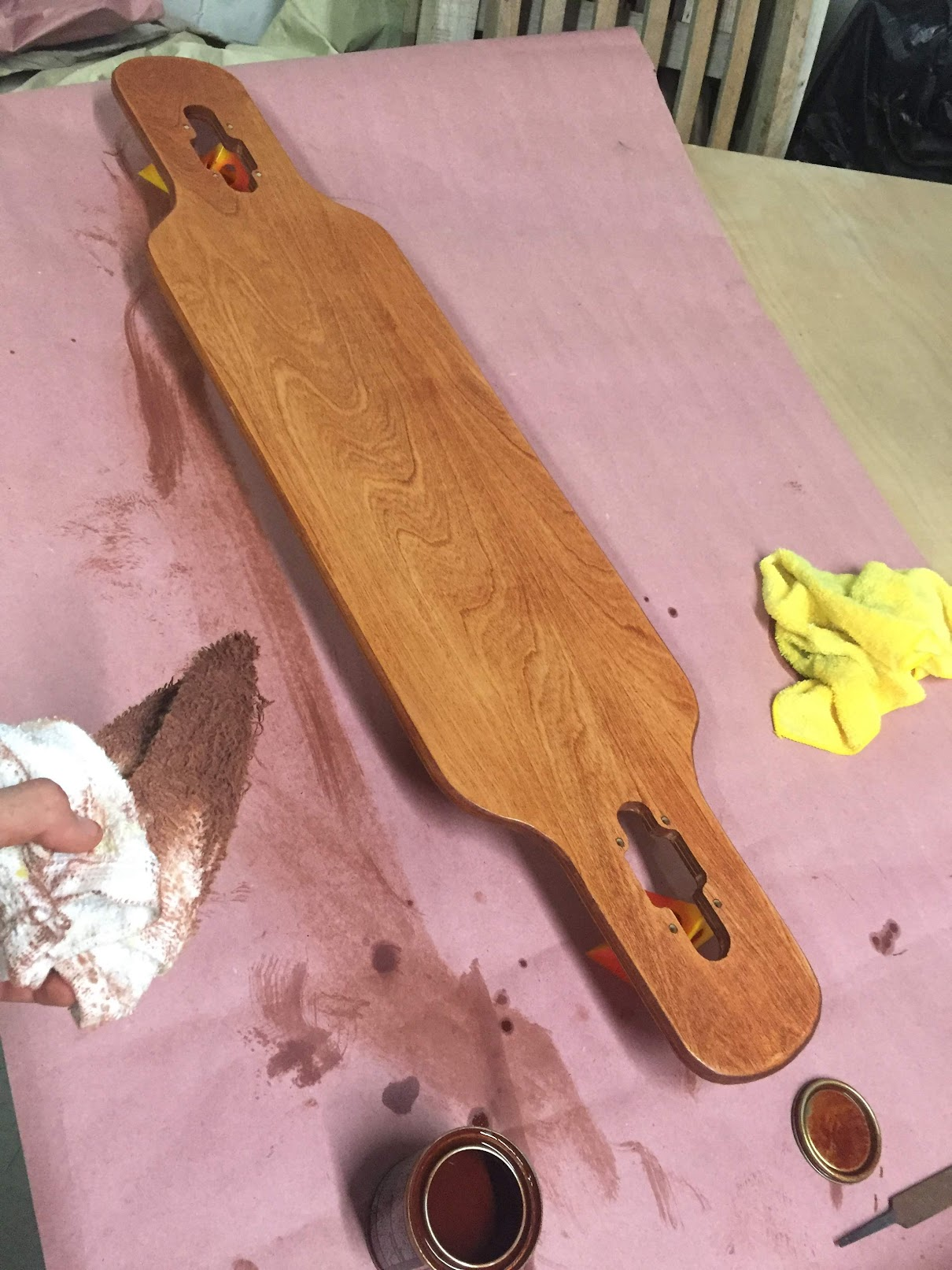
I laminated my own plywood using some realy heavy pieces of stock instead of a vacume bag. Then I cut, sanded, routed and finished the longboard. I used it get to school everyday for two years
Solar Longboard
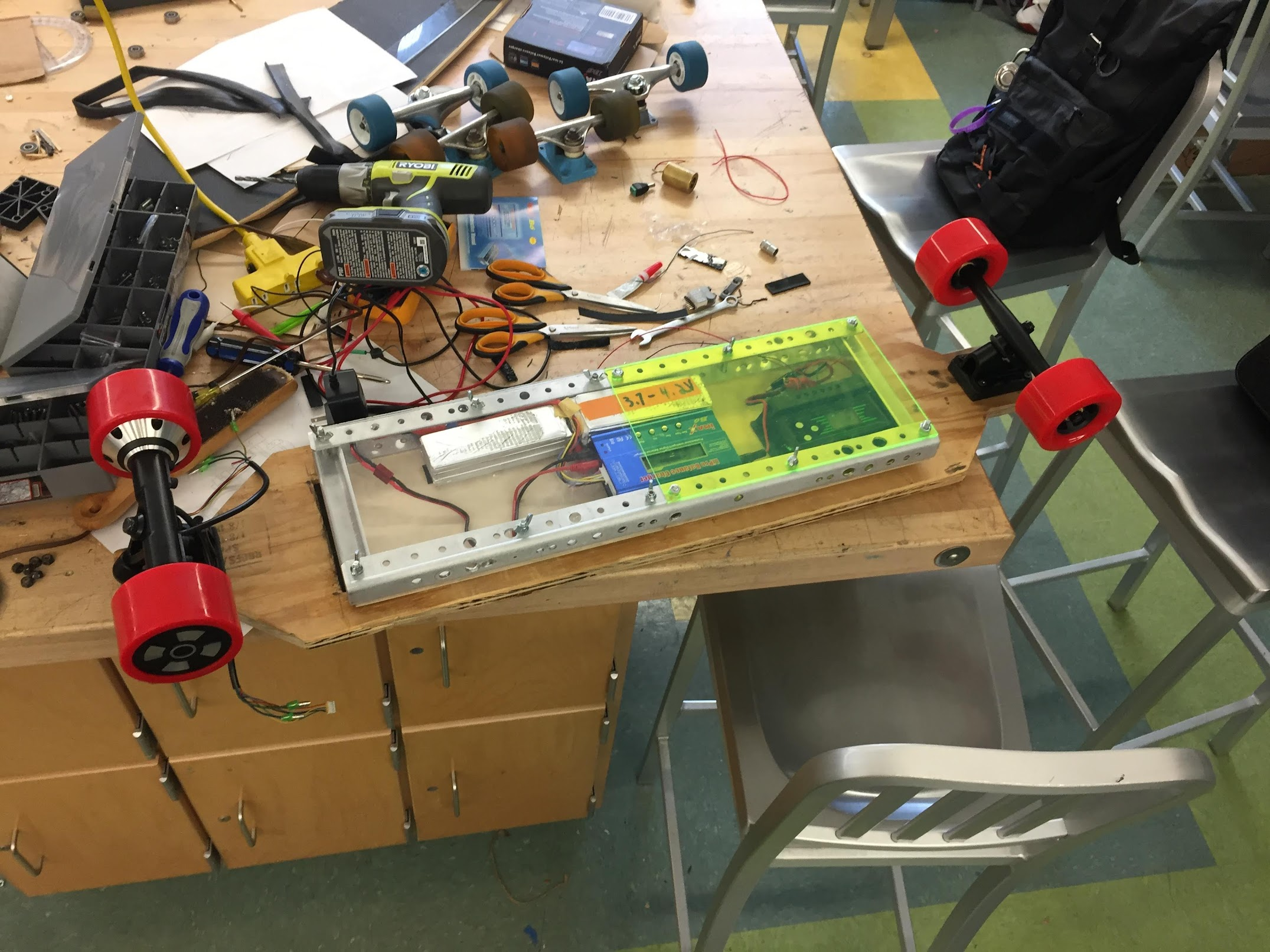
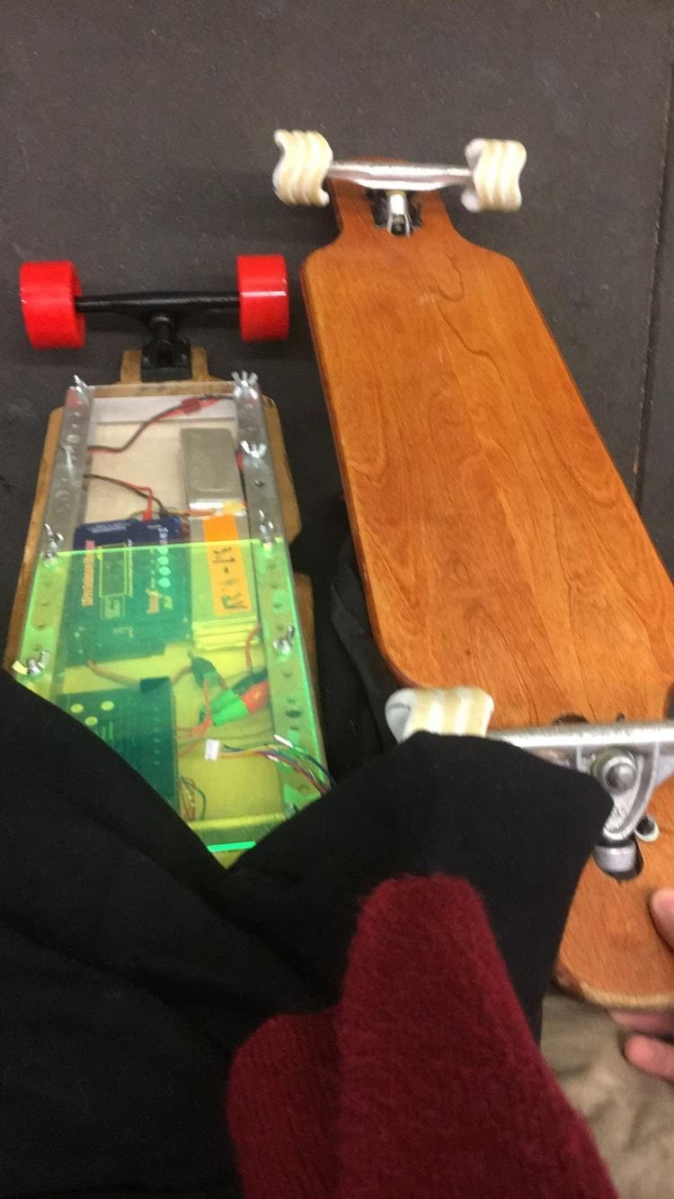
In high school I made an electric longboard that had a decently large strip of solar panels along with a regulator for charging a lipo battery pack. The rest of the board was cheap off the shelf e-skate components mounted to a piece of crappy plywood I cut with a jigsaw.
Music with LEDs
LED Mushroom
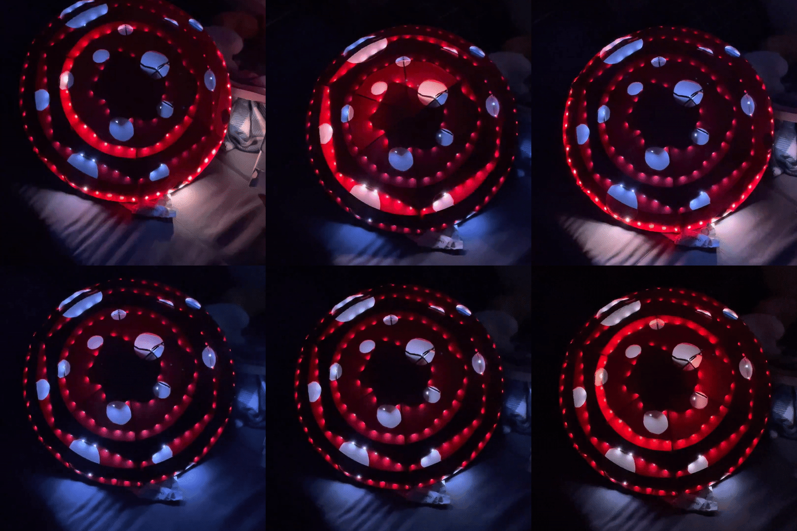
This mushroom syncs with music over wifi using an esp8266 and the WLED library.

LED Eye
TIP31C
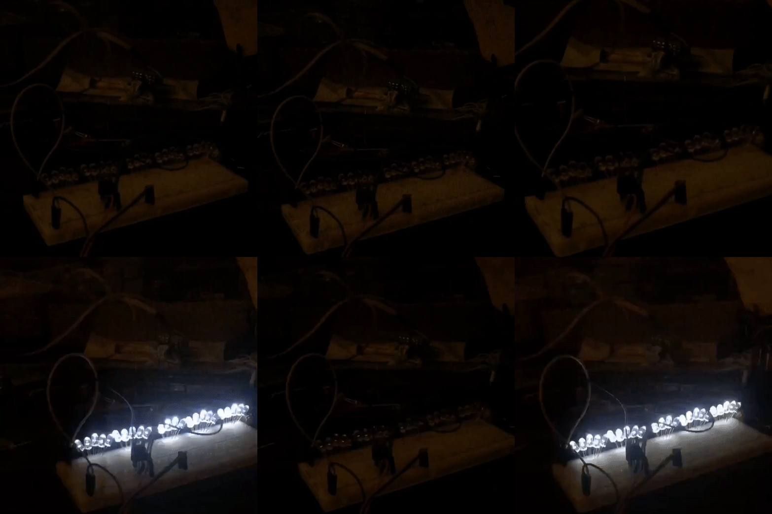
One of my favorite LED projects is using TIP31C NPN transistor to visualize an audio signal.
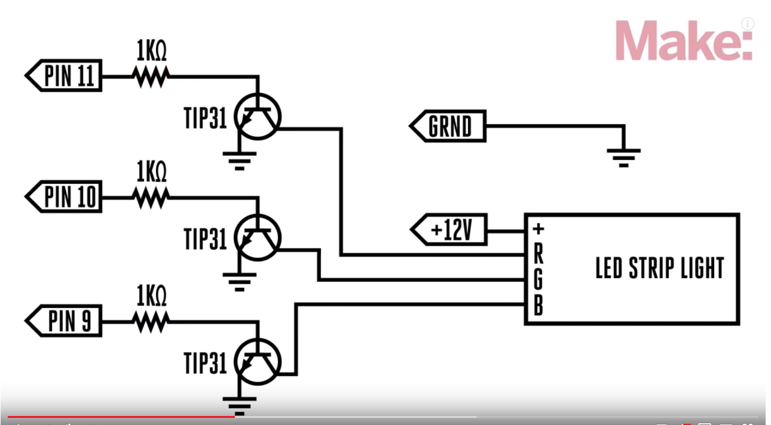
Video is a lot cooler with sound ofc.
Bicycles
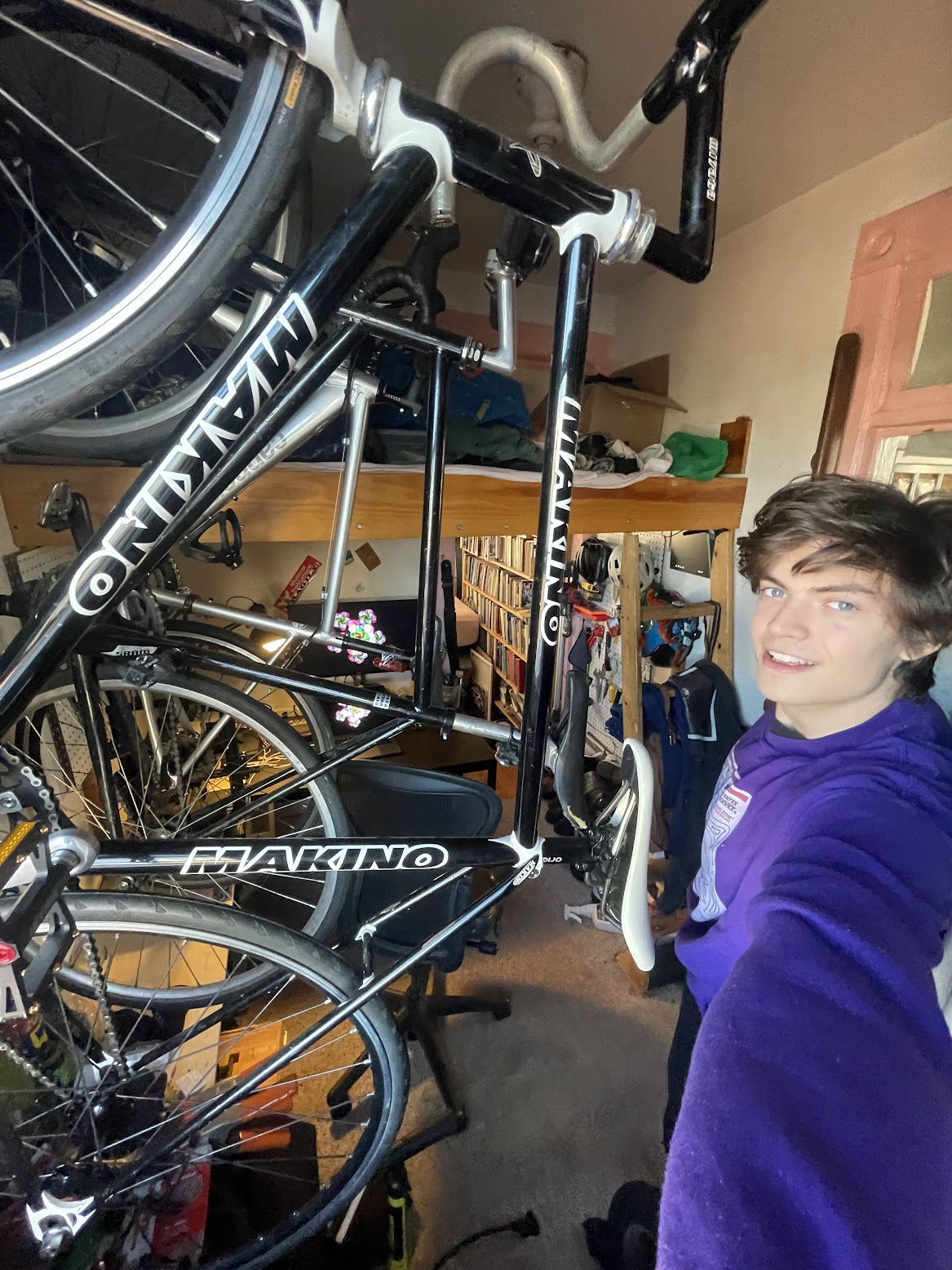
I love bicycles. I’ve been riding them since I was four and to this day they are my favorite form of catharsis because they combine working with my hands, exploring and exercise.
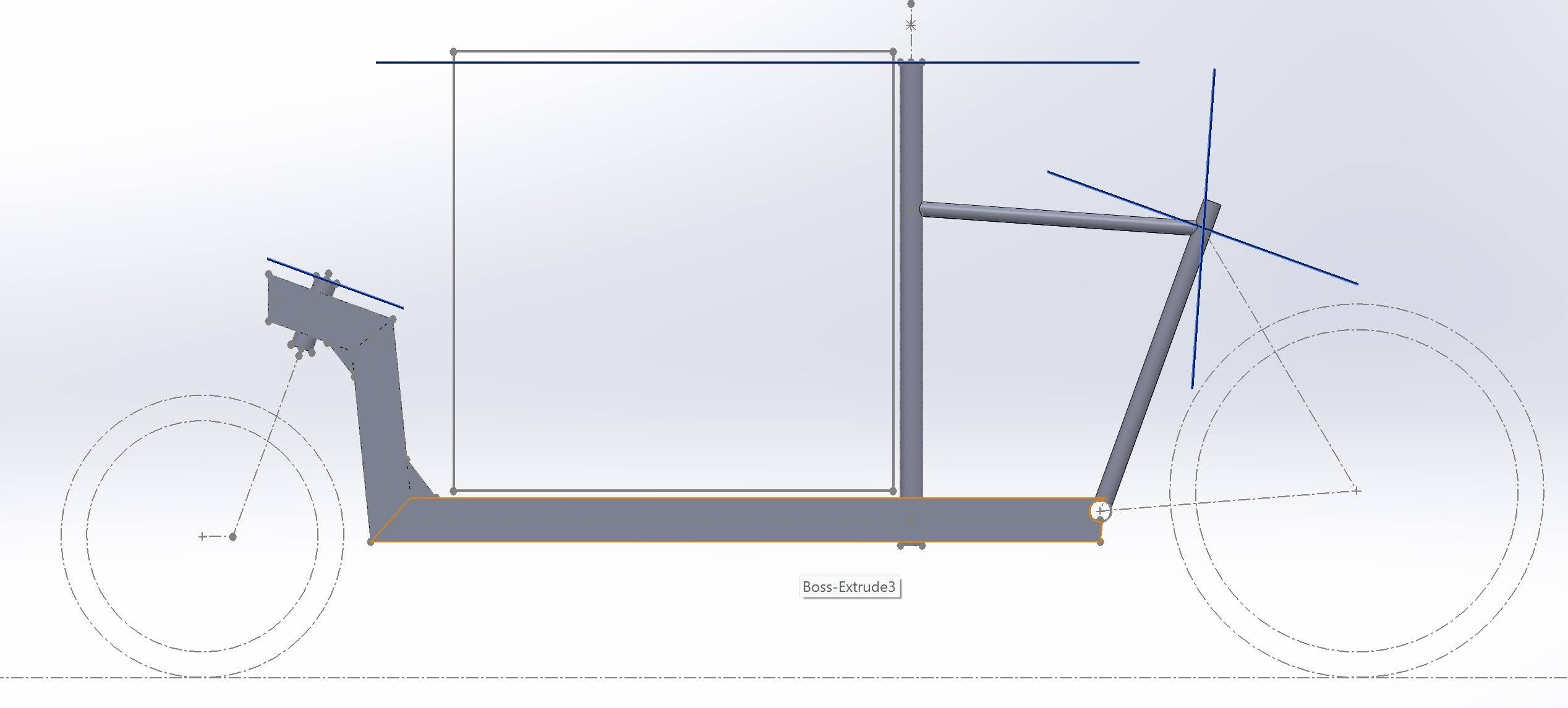
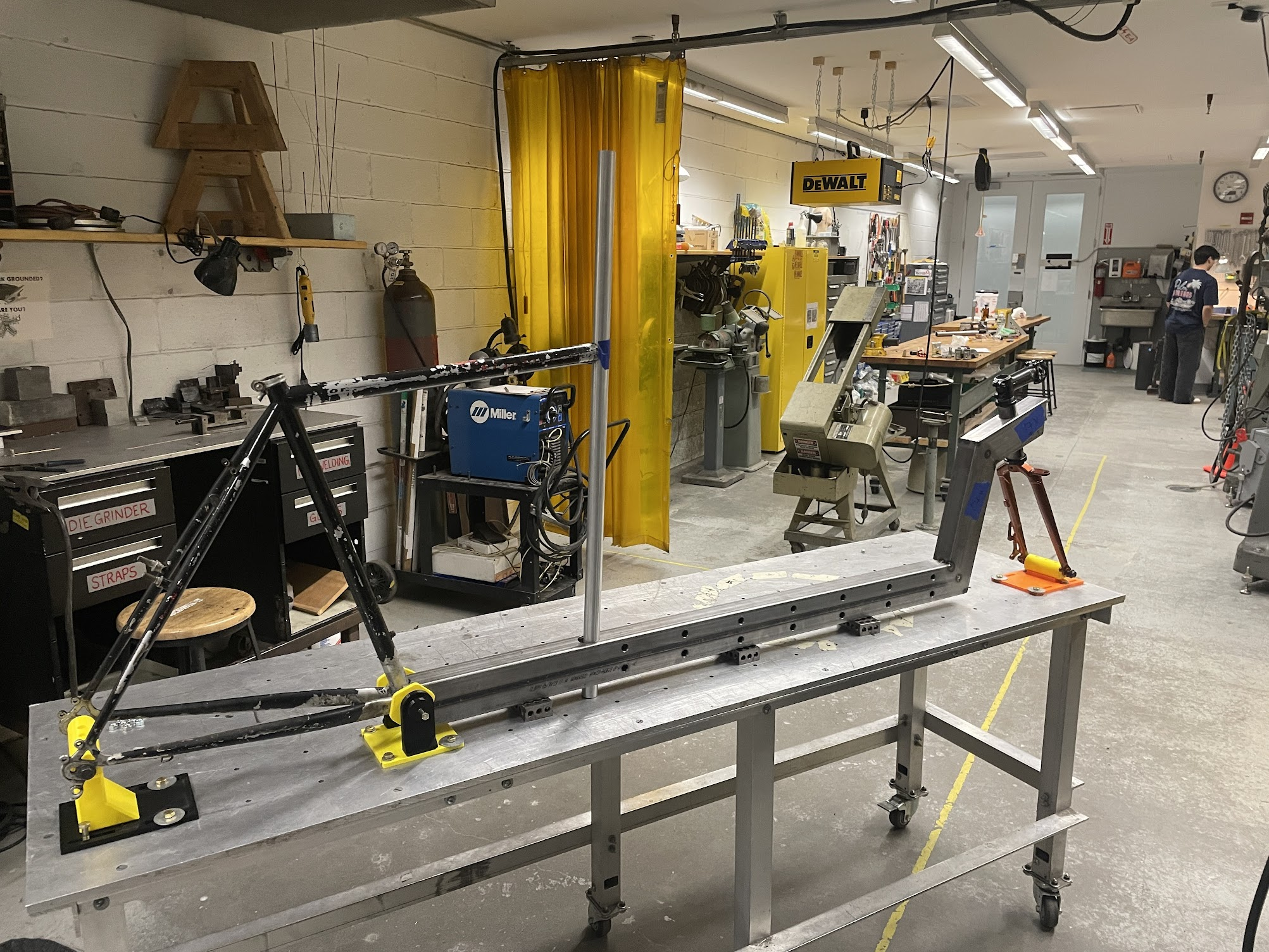
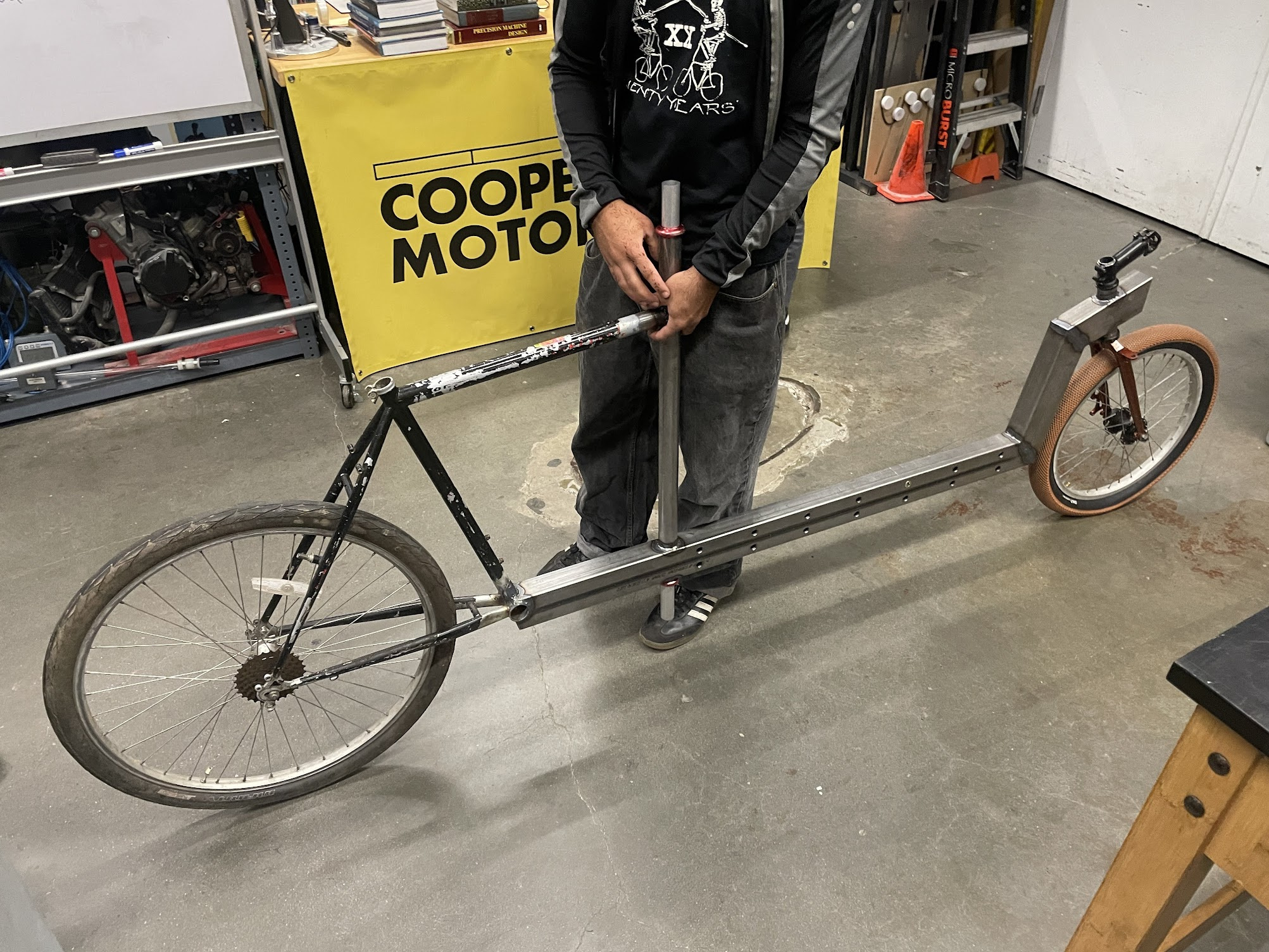
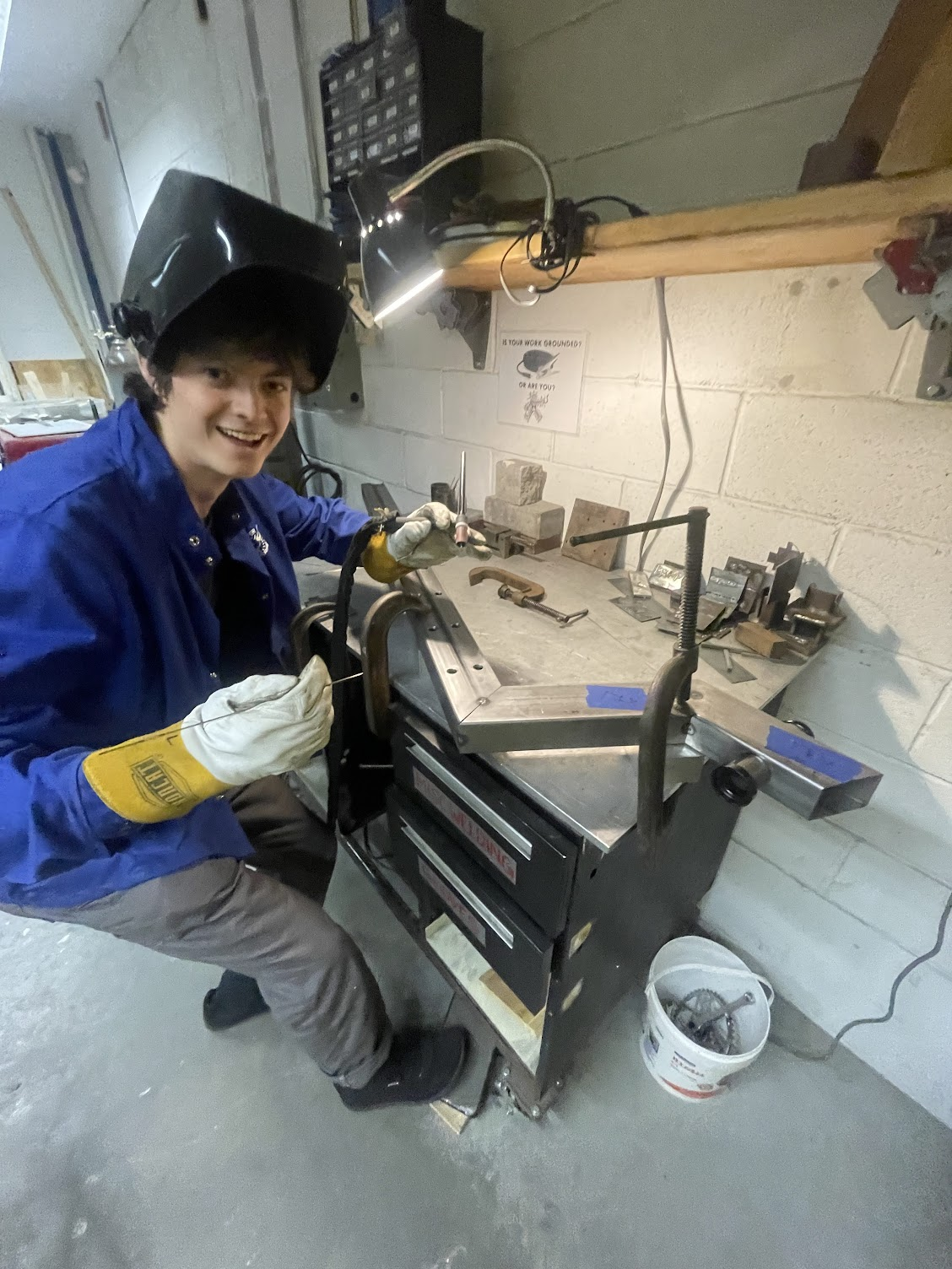
Building a cargo bike
Carbon fiber Seatpost
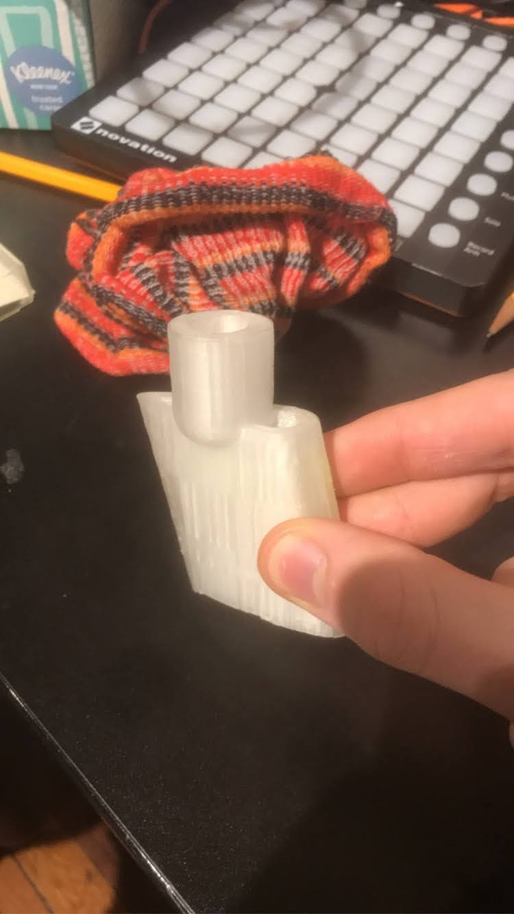
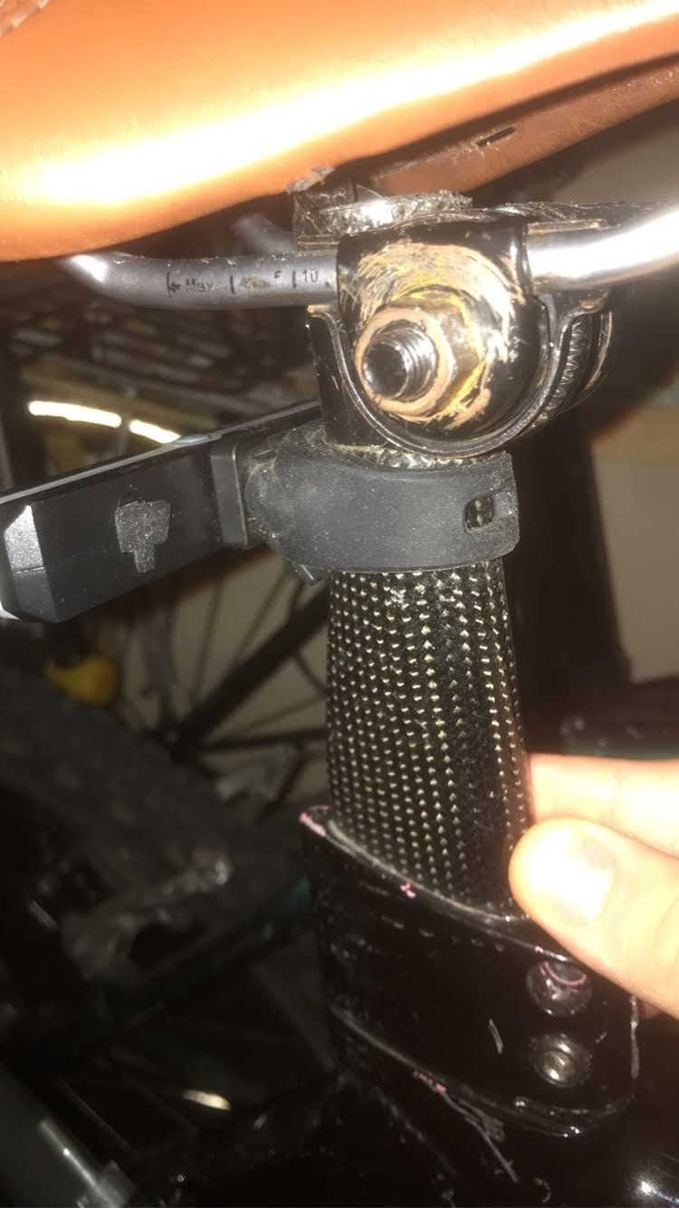
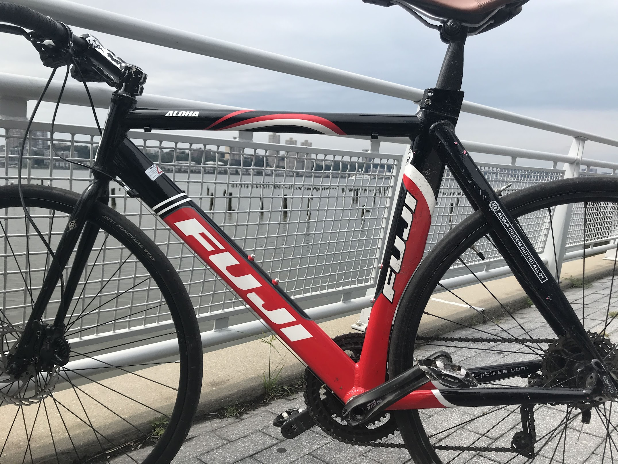
This was my first ever CAD project. The bike frame I bought for cheap turned out to have no seatpost with it. I couldn’t find the proprietary part or drawings for it anywhere on the internet. I thought I might be able to 3D print a bicycle seatpost. Ended up using a 3D print as a core mold for a carbon fiber layup.
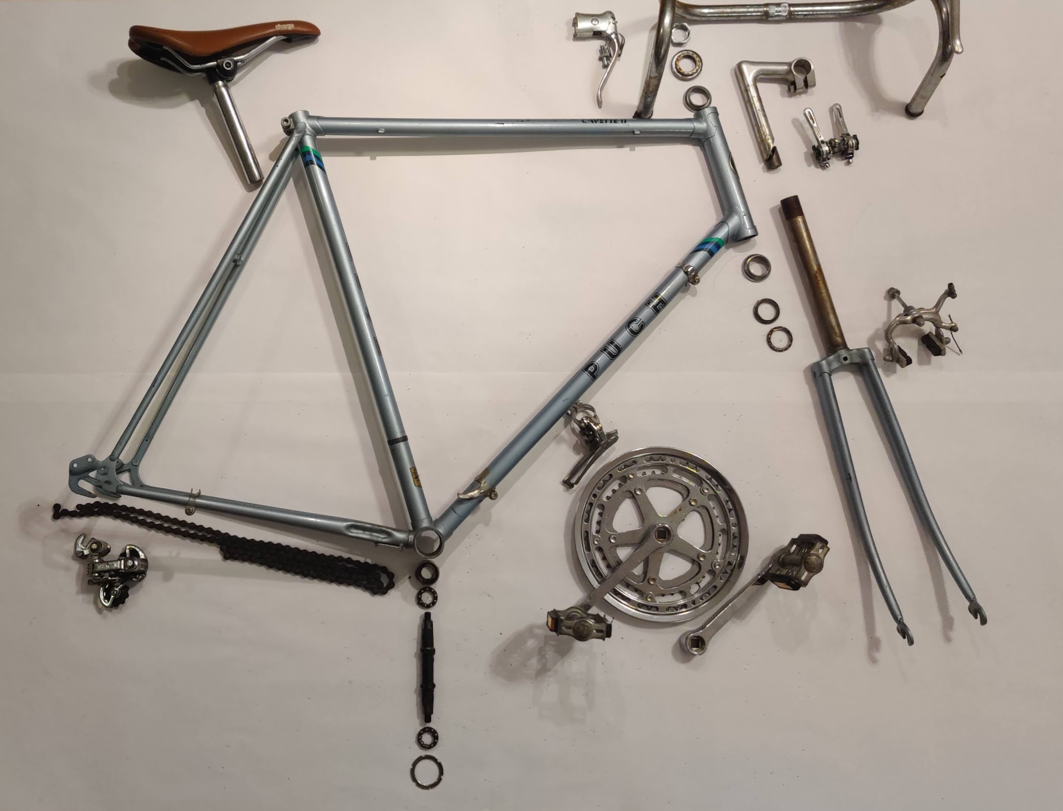
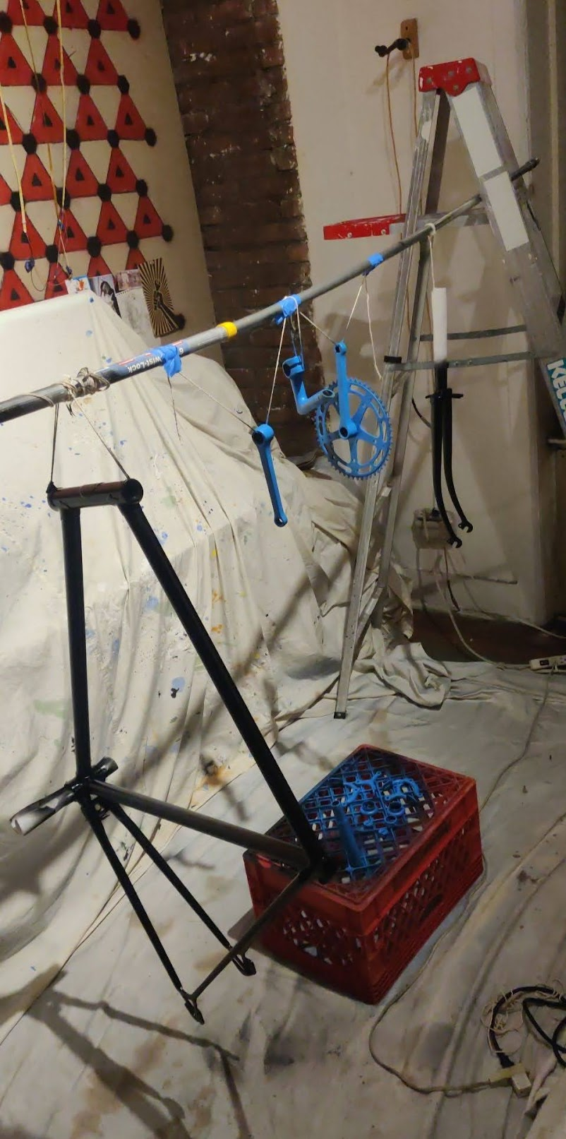
Craigslist bike Restorations

High School E-Bike
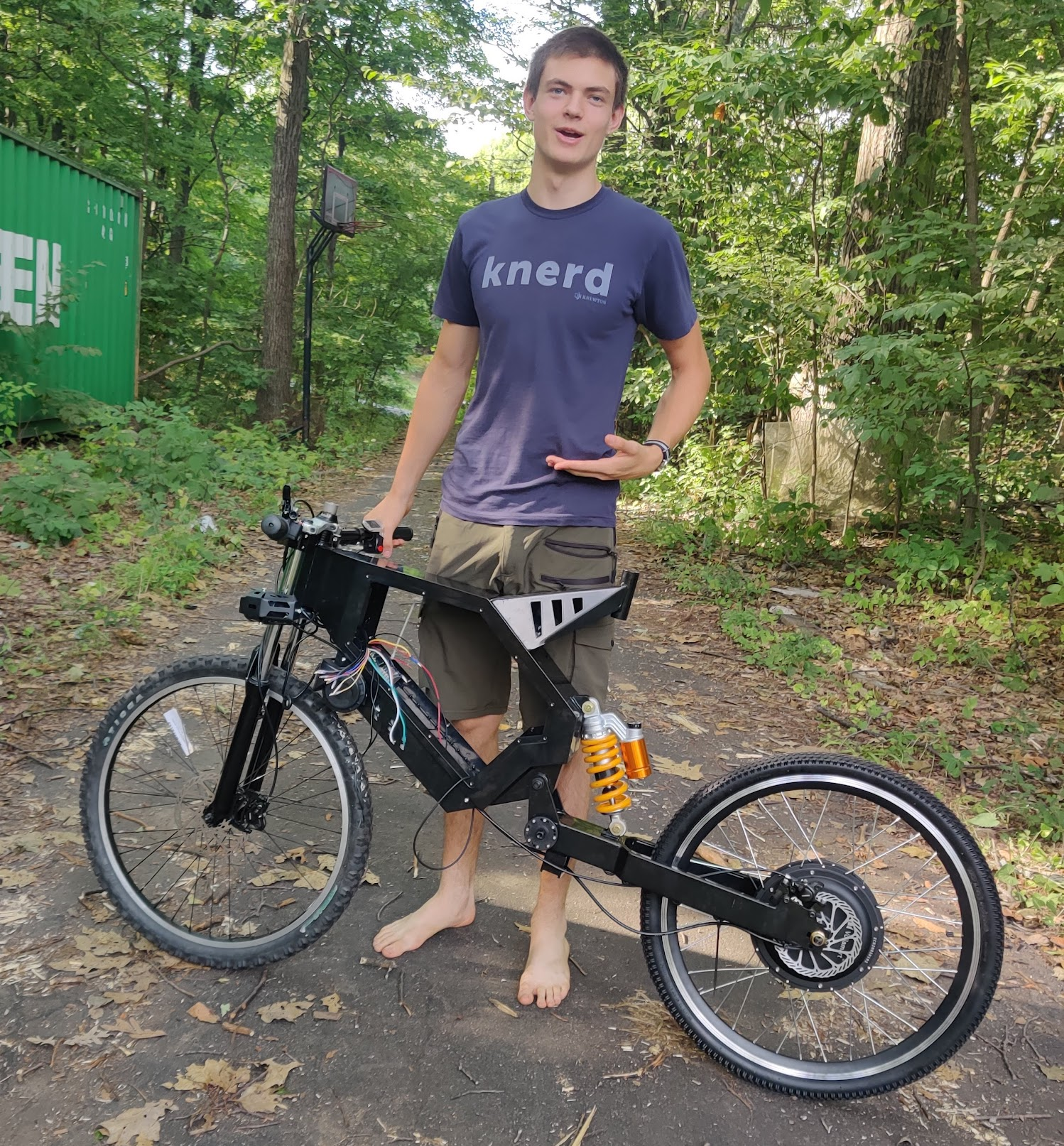
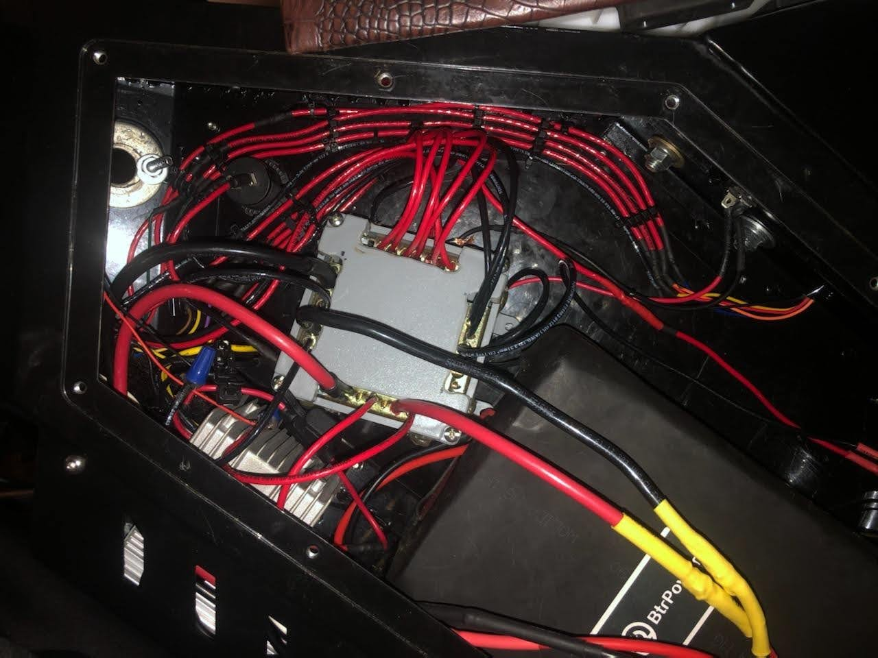
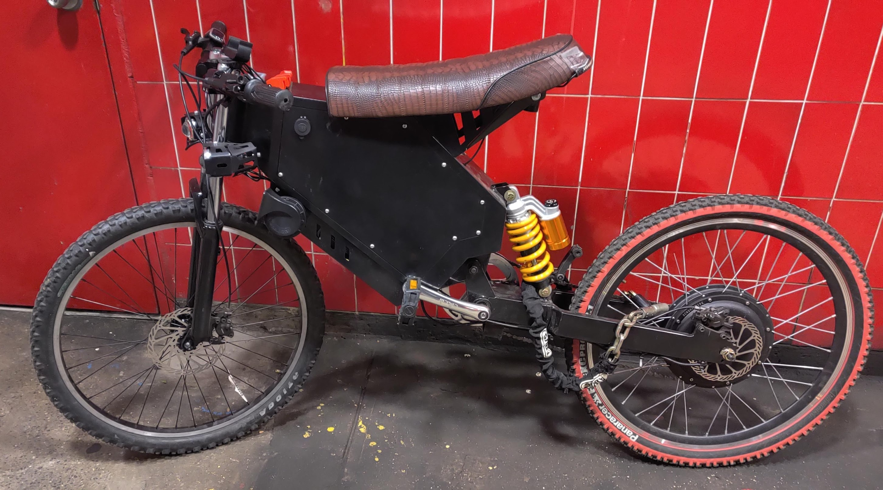
My Lovely Track Bike
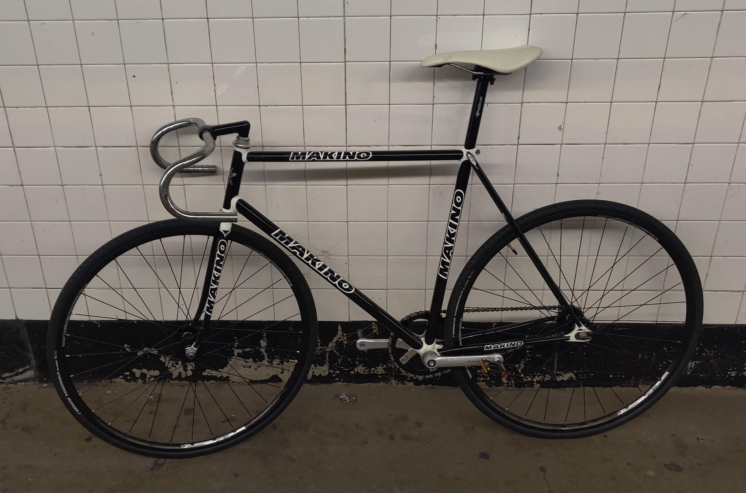
iPhone Repair Business
Music Reactive Logo


Small Assembly
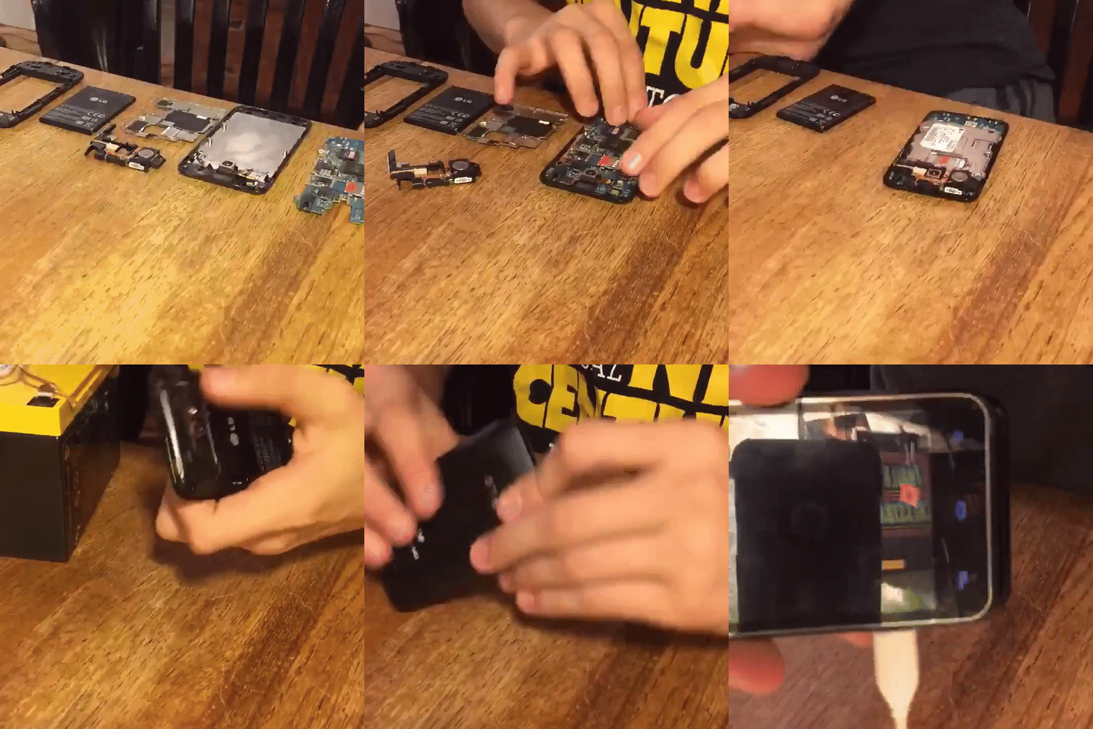
Collected Broken LCDs

My Rummagings
I love rummaging through interesting garbage and seeing what nice electronics I can shuck or do light repairs on to get functional. Through this habit I’ve found multiple phones, TVs, Sound Systems, Bicycles and various other nicknacks.
